Hi and sorry for the stupid question. 😱
How difficult is it to add a working coaxial SPDIF output to a typical device which uses the PCM56P? Is it just a matter of grabbing the incoming data line to the PCM chip, or does it need to be merged with other lines or formatted by some additional specialty chip?
I've been fishing around, but most of the threads and info I can find are for something a bit more elaborate than what I was thinking of doing.
Thanks!
George
PS- I'm not assuming that skipping the analog output circuitry is something I'll actually like listening to. I'm just curious to hear it.
Bump on this if anybody knows anything or needs any more details. 😕
Going back and looking at the PCM56P datasheet again, I'm guessing if there's a way to do it, it's unfortunately not going to be as simple as stealing the incoming data from the DA chip. The PCM's got a separate clock line, a latch signal, and an audio stream coming in which looks to be in chunks of 16bits. I remember the SPDIF stream being much higher with all the extra junk (32 or something).
Is there a chip which does this, and does anyone have any helpful schematics for any other gear which uses a PCM56P and spits out SPDIF? If it's too hard to do, I'd still be interested in seeing how.
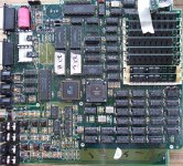
BTW, it's a Peavey DPM SP sample playback module. The PCM chip actually receives some sort of merged stereo stream and outputs the converted signal to a multiplexer chip (CD4053) which somehow splits it back to two channels again. Looks like it is fed directly from one of those million pin Motorola DSP chips.
Thanks,
George
Going back and looking at the PCM56P datasheet again, I'm guessing if there's a way to do it, it's unfortunately not going to be as simple as stealing the incoming data from the DA chip. The PCM's got a separate clock line, a latch signal, and an audio stream coming in which looks to be in chunks of 16bits. I remember the SPDIF stream being much higher with all the extra junk (32 or something).
Is there a chip which does this, and does anyone have any helpful schematics for any other gear which uses a PCM56P and spits out SPDIF? If it's too hard to do, I'd still be interested in seeing how.
BTW, it's a Peavey DPM SP sample playback module. The PCM chip actually receives some sort of merged stereo stream and outputs the converted signal to a multiplexer chip (CD4053) which somehow splits it back to two channels again. Looks like it is fed directly from one of those million pin Motorola DSP chips.
Thanks,
George
I'm uncertain about what you wish to accomplish. Do you wish to tap the three wire digital audio signal feeding the DAC chip and transmit them out as an S/PDIF signal?
You need a S/PDIF transmitter chip such as TI DIT4192 or Cirrus CS8406. To drive a coax output, you will also need an analog section capable of converting the TTL level output and driving it at 0.5 Vpp with 75 Ohm output impedance. Optical is easier since you just take the TTL output of the chip and connect it to the TOSLINK transmitter device's digital input.
Thanks guys!
Ken, yeah that's about it (I'm trying to grab it before it gets converted). Apparently, I've already looked at that Cirrus chip. I tried to save the datasheet in my Peavey DPM folder and there was already one in there. 😀
Macboy- I'll go back and read through it and look for some example circuits on the web. Do you know right off if the original digital feed can be re-output by that 8406 chip if I wanted to keep both, or do you have to split/buffer the lines with another chip?
Thanks Again,
George
There should be no issue in using both the existing DAC and the new S/PDIF transmitter at the same time. You can just 'tap' into the data and clock signals going into the DAC. Keeps the wiring as short as possible to minimize capacitive loading. If you have a nice fact oscilloscope, it wouldn't hurt to verify the quality of the signals at the inputs to both the DAC and S/PDIF chip after making the mods.
Thanks Macboy,
That sounds good. I thought I'd screw the signal quality all up if I sent it to two places like that. May take me a bit to try it as I'll need to get one of those Cirrus chips and whatever else might be needed for clean output (think I saw transformers on some stuff). Scope should be no problem. I just bought my first digital and am looking for things to look at.
I've actually got a couple AD1856N-K DAC chips on the way here. The Peavey has two stereo output pairs. I may try etching a piggyback board I can plug into one of the PCM56 sockets with the Analog Devices chip and the SPDIF stuff. That way I'll have two different DAC sounds and a digital out to pick from.
Take Care
George
I hate to have to ask this, but if anyone here is experienced with the PCM56P and CS8406 and has a minute to offer any suggestions, it would be a big help.
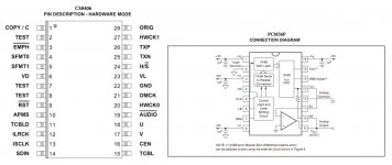
The 8406's "3-wire serial" input method appears to use the ILRCK, ISCLK, and SDIN pins. I'm guessing the "Serial Audio Bit Clock" (ISCLK) corresponds to the "Clock Input" of the PCM56P and the "Serial Audio Data" (SDIN) line is obviously the same as the "Serial Data Input", but can "Serial Audio Input Left/Right Clock" (ILRCK) be set up to recognize the same signals which are fed to the PCM56's "Latch Enable" input, or does that need to go somewhere else in the Cirrus chip?
I'll also likely end up needing help with how to setup the 8406 hardware mode's user/config pins for what the PCM56 was receiving and any other tips on keeping all the lines stabile.
I've got a feeling that if I can manage to get this to work at all, it won't happen on the first try, but for the chip's sake, I'd like to avoid screwing the circuit up so bad that I end up having to desolder the 8406 and do a whole new board.
Thanks, and again, sorry for needing so much help on this!
George
PS (additional info)- The PCM chip here handles both channels which are then split back to stereo by a 4053 chip. All chips are socketed. My goal is to etch a piggy-back board which can be inserted in the original PCM socket, which will hold the 8406, the SPDIF transformer and resistors, and a new socket for the PCM chip. The 8406 will be getting whatever power lines it needs from the same lines the PCM was using.
Attachments
I hate to have to ask this, but if anyone here is experienced with the PCM56P and CS8406 and has a minute to offer any suggestions, it would be a big help.
Before you dig yourself into a deeper hole you really should read and understand the CS8406 datasheet. There is a lot more to this than matching signal names. It would be much easier to convert the analog output of the synth to digital via a sound card or other A/D device.
Hi Tam Lin,
Yeah, I've been looking at that and the PCM56 datasheet over the past day or two, it's just moving really slow.
If the signals being fed to the PCM actually are incompatible with those which the 8406 is able to be configured for (without additional chips), I'll understand, but if they can work together somehow, it would be good experience to try to get that happening.
George
You'll almost certainly require some additional chips, perhaps even a CPLD. From a quick look at this there will be two challenges - the first is getting the right frequency for the OMCK pin of the 8406, Second, and perhaps the greater of the two - working out how to get the correct timing of the framing (WS in I2S parlance) signal.
Fig7 in the PCM56 DS shows that for each audio sample output, there needs to be a cycling of the LE pin. However one chip is doing double duty so there are two cycles of the LE pin per audio frame. None of the standard digital audio formats have two cycles of the framing pulse per audio frame, they have just one. So somewhere you'll need a divide by 2 function i.e. a flip-flop. You'll need to be a logic designer to get this to work.
Fig7 in the PCM56 DS shows that for each audio sample output, there needs to be a cycling of the LE pin. However one chip is doing double duty so there are two cycles of the LE pin per audio frame. None of the standard digital audio formats have two cycles of the framing pulse per audio frame, they have just one. So somewhere you'll need a divide by 2 function i.e. a flip-flop. You'll need to be a logic designer to get this to work.
Thanks abraxalito. I guess that's out then. 🙁
I didn't realize there were that many combinations being passed around between some of the common chips, and had probably given the 8406 too much credit. I thought it could work with most of them on its own and it was just a matter of setting the control pins for it.
Thanks Anyhow,
George
I didn't realize there were that many combinations being passed around between some of the common chips, and had probably given the 8406 too much credit. I thought it could work with most of them on its own and it was just a matter of setting the control pins for it.
Thanks Anyhow,
George
From a discussion some months ago, there was an ancient CD player which used a Sony digital filter to drive a PCM56P and that Sony chip also has an S/PDIF output. If your unit was lucky enough to use that same Sony chip you'd have a simple solution.
Unfortunately, mine are being fed directly from a big DSP chip. Got a feeling it probably could have handled that task as well, but only if the designers intended it to.
George
PS- I saw a few things when I was looking which also used a single PCM56 for both channels @44.1/16bit. I'd have thought that was more common and that the popular SPDIF transmitters would know what to do with it.
George
PS- I saw a few things when I was looking which also used a single PCM56 for both channels @44.1/16bit. I'd have thought that was more common and that the popular SPDIF transmitters would know what to do with it.
Multibit DAC chips these days are definitely in the minority since S-D DAC chips are much cheaper to produce and suit digital foundry processes. I'd be interested to know of any relatively modern kit using PCM56 or similar.
Agree with the assessment provided by Abraxalito. The input / implementation for the CS8406 is super simple provided you have an I2S interface to drive it. If you want one I can post it for you - the PCB is 2 by 3 inches. The implementation only remains simple if you have a standard I2S stream including LRCLK, MCLK and DOUT.
The PCM56 data stream would require some modest massaging to get it close to this form. Quite possibly the easiest way to achieve this would be using a micro like a PIC, as this would allow you to clock in the audio data using one serial I/O port and pump it out as SPI on another port - which could fairly conveniently drive an SPI to SPDIF output.
You would need to be quite careful with clock rates and the implementation in the PIC, particularly relating to the choice of crystal frequencies, but I think this would be "doable".
As an aside, have you been able to dig into what other interfaces and data ports exist on the DSP in the system?
There does come a point however where you are easiest cutting your losses...
Unfortunately, mine are being fed directly from a big DSP chip. Got a feeling it probably could have handled that task as well, but only if the designers intended it to.
George
PS- I saw a few things when I was looking which also used a single PCM56 for both channels @44.1/16bit. I'd have thought that was more common and that the popular SPDIF transmitters would know what to do with it.
No it is definitely not common to use a single DAC for two channels. This was obviously a cost saving exercise from the early days of digital audio when a high quality (for the time) DAC like the PCM56 was quite expensive.
I have to admit that when I first replied to this thread, I didn't pay much attention to the details of the PCM56; I assumed it was an I2S input device, but it is not.
This can be done, but it is not straightforward. You have the data and clock, and those should be OK. I'd check if both devices use the same edge: rising or falling; if not, invert the clock. You will need the Word Clock (WCLK or LRCLK) and a master clock. Your system may have a suitable master clock, or you may need to use a frequency multiplier chip (e.g. ICS511) on the bit clock to derive a master clock for the CS8406. Even then this will only work if your system's bit clock is continuous, not bursting. With some clever work, you can derive the WCLK from the LE signal and the enable signals for the sample/hold circuits.
You will need to make use of the oscilloscope you just bought to visualize the various signals, both the ones provided in your system and the ones you will need to create/derive. You can compare them to the timing diagrams in the data sheets to ensure that the timing and polarity of the signals looks OK.
Thanks for all the info guys. Even while not being able to do what I planned, I'd like to learn more about it.
It is fun to look at and learn from. They've got a whole army of logic chips in there. I wasn't even aware that those multiplexer chips were used for stuff like that (reconstructing analog audio). I'll poke around in it some more to see what's there and what's hitting the PCM chip. When I looked at it before, I'm not sure I got valid results. The signal I got off the clock line was way up in the 8.x MHz range and the latch was repeating at a rate of 125kHz, IIRC.
Thanks again to all,
George
I should have specified there- None of this stuff would be considered modern by digital standards. The sampler and a couple others here are all from around 1990-91, and the things I ran across online were either similar (old music hardware) or fairly old CD players.I'd be interested to know of any relatively modern kit using PCM56 or similar.
Yes (if it's not too much trouble), I'd like to see it. After the d.out for the sampler idea was shot, I thought about adding a compatible ADC to the 8406 and sticking it in a mic pre or something here, but even the stuff I could find on that was way more elaborate than a pair of chips.The input / implementation for the CS8406 is super simple provided you have an I2S interface to drive it. If you want one I can post it for you - the PCB is 2 by 3 inches.
Unfortunately, no. I was surprised that I was able to get service docs at all for this thing, but they're not much more than some rough scans of the schematics. There are a couple notes scribbled on them about what frequencies to expect at different points, but nothing as specific as data formats,etc.As an aside, have you been able to dig into what other interfaces and data ports exist on the DSP in the system?
It is fun to look at and learn from. They've got a whole army of logic chips in there. I wasn't even aware that those multiplexer chips were used for stuff like that (reconstructing analog audio). I'll poke around in it some more to see what's there and what's hitting the PCM chip. When I looked at it before, I'm not sure I got valid results. The signal I got off the clock line was way up in the 8.x MHz range and the latch was repeating at a rate of 125kHz, IIRC.
Thanks again to all,
George
Attachments
Hi,
I have attached a screen-dump of the CS8406, and also the PCB. If you want the ALTIUM files, just email me.
These interface to an ADAU1442 DSP (which has one tiny bug that does not set a bit in the SPDIF stream that I really wanted set!).
I really wanted to drive the DSP into the SPDIF input of my PC, and the damn PC was ignoring the data! The design below was "quick and dirty" - the layout is not super great but then again, it is a pretty simple circuit.
The CS8406 is driven by:
LRCK
SCLK
SDIN
MCLK (a multiple of SCLK - usually 64-256 Fs)
Looking at your application, you would have to be generating MCLK also. You could go a PLL, or as I suggested use a micro to receive the data and generate all these clocks for you. On a bit of thought, you would probably end up having to implement an ASRC in software to go with all the other bother you have too...
So onto your question of using an ADC and 8406 to make an SPDIF ADC...
How hard would it be to hook this up to a ADC and have an SPIDF output from the ADC? Dead simple. Relatively speaking - using the CS5381 ADC. Caveats below...
I have attached a schematic of the ADC that I use - which interfaces to the same DSP. In this application I have set the ADC to SLAVE mode, and it receives MCLK, LRCLK and SCLK from the DSP.
In MASTER mode, you simply need a 12.288MHz oscillator, and it generates LRCLK, SCLK and DOUT. If you connect these, and the MCLK, to the CS8406, hey presto you have a SPDIF ADC. No need for big clunky DSPs and stuff, not even one line of software. You can set it all by jumpers.


All these boards use copper one one side, tracks on the top and a few wire links here and there. I have done this as I tend to make the prototypes using "press and peel" film.
- I would not recommend doing this as pure single sided - it will work, but you might end up with degraded noise performance
- When I said "easy" above, the above design is not for someone who is learning the ropes. There is some moderately high speed digital stuff, and layout that will take a bit of care. That said, it does not require any supporting logic or microcontroller to set up - so you can get this going without much mucking around.
Some notes of caution:
- Some PC sound cards sample at a fixed rate and use an ASRC on the input. You can see the artefacts of this in the noise spectra as a smear of spurs (a long way down I do concede, but they are there)
- You might want to crank up the sample rate - I have not played with this, and am not sure at the sample rate PC interfaces will take. I am sure someone will know though.
I have attached a screen-dump of the CS8406, and also the PCB. If you want the ALTIUM files, just email me.
These interface to an ADAU1442 DSP (which has one tiny bug that does not set a bit in the SPDIF stream that I really wanted set!).
I really wanted to drive the DSP into the SPDIF input of my PC, and the damn PC was ignoring the data! The design below was "quick and dirty" - the layout is not super great but then again, it is a pretty simple circuit.
The CS8406 is driven by:
LRCK
SCLK
SDIN
MCLK (a multiple of SCLK - usually 64-256 Fs)
Looking at your application, you would have to be generating MCLK also. You could go a PLL, or as I suggested use a micro to receive the data and generate all these clocks for you. On a bit of thought, you would probably end up having to implement an ASRC in software to go with all the other bother you have too...
So onto your question of using an ADC and 8406 to make an SPDIF ADC...
How hard would it be to hook this up to a ADC and have an SPIDF output from the ADC? Dead simple. Relatively speaking - using the CS5381 ADC. Caveats below...
I have attached a schematic of the ADC that I use - which interfaces to the same DSP. In this application I have set the ADC to SLAVE mode, and it receives MCLK, LRCLK and SCLK from the DSP.
In MASTER mode, you simply need a 12.288MHz oscillator, and it generates LRCLK, SCLK and DOUT. If you connect these, and the MCLK, to the CS8406, hey presto you have a SPDIF ADC. No need for big clunky DSPs and stuff, not even one line of software. You can set it all by jumpers.
All these boards use copper one one side, tracks on the top and a few wire links here and there. I have done this as I tend to make the prototypes using "press and peel" film.
- I would not recommend doing this as pure single sided - it will work, but you might end up with degraded noise performance
- When I said "easy" above, the above design is not for someone who is learning the ropes. There is some moderately high speed digital stuff, and layout that will take a bit of care. That said, it does not require any supporting logic or microcontroller to set up - so you can get this going without much mucking around.
Some notes of caution:
- Some PC sound cards sample at a fixed rate and use an ASRC on the input. You can see the artefacts of this in the noise spectra as a smear of spurs (a long way down I do concede, but they are there)
- You might want to crank up the sample rate - I have not played with this, and am not sure at the sample rate PC interfaces will take. I am sure someone will know though.
Appreciate it Googlyone!
I'll be looking over those pictures.
Did you ever get any idea of why the PC wouldn't see that stream? I've been following the whole "onboard SPDIF" thing since back in the days of the ISA Epoch sound card and have been impressed at how they've refined it and it's become so common these days. I've usually only used it on stuff here for output. I can imagine the SPDIF input/external sync thing might be a bit more messy.
George
- Status
- Not open for further replies.
- Home
- Source & Line
- Digital Source
- Adding S/PDIF output to PCM56P?