The use of written language without looking into the other person's face, always has the potential for misunderstandings. That's why emoticons are used but they do not help entirely.
I don't think anyone here is telling you what to do or not, those are merely suggestions and you are free to take of all that what you prefer.
Actually, just because I find one design superior to another (even possibly with good arguments) doesn't mean you cannot built the inferior design and be happy with it.
On the other hand, your approach "...the main reason is that I want to know WHY I should do something, WHY your suggestion is better, HOW it will improve my design, not just, "you should do this because it's obviously better and I'm an expert"..." is perfectly valid. That's how we all learn. By trying to understand WHY something works.
My opinion is that if I try to convince you that one design is superior to another, I should also give you the rational behind that. That's at least the theory. In practice this could lead to very long posts and not all of use are willing to spend that time/effort (and that's their own choice - period).
Now back to the your gain stage.
By using a constant current source as load and a cap-bypassed resistor at the cathode, you can achieve maximal gain (almost mu). If you are not afraid of a bit silicon that's easy to implement. A pentode might work as CCS, too if you do not like sand.
You could also use a constant voltage sink in the cathode (a simple LED is a good enough approximation).
The nice think about the CCS is that you can easily change the current through the tube and see what you prefer (if your CCS is variable).
I had so far very good experience with that - and I liked what I heard.
But don't take my word for it - try it out yourself, it's easy.
Martin
PS: I am obviously too slow - my post got a bit redundant
"My opinion is that if I try to convince you that one design is superior to another, I should also give you the rational behind that."
I like your way of thinking, however I also realize it might take a lot of time as you said.
You said a pentode might work as a ccs, if I'm thinking correctly you mean I'd keep my existing 12AU7A but then have to add a pentode just for the CCS of the 12AU7A? If so then I'm going to have to decline on that idea because if I have to go buy a whole other tube and socket, it will be to replace the 12AU7A instead of help it (unless of course I just make another gain stage which I might).
You could use it as a Cathode follower after your input stage which would give you the same result.
A CCS would be a silicon beast - which I would have no issue with - but you obviously do.
Consider a higher mu triode - this should work since the sweep tube should represent a fairly easy load. Alternatively consider a nice pentode driver, my goto pentode is the 6AU6 which combines reasonable drive current and good gain.
Shoog
I've heard the term cathode follower used before but I don't know much about it. Let me take a crack at it, it derives its signal by capacitive coupling between the cathode and the cathode resistor of the previous tube? (hopefully I'm close) Which goes back to my other huge question of whether or not inverted signal matters, I suppose it does because deriving the signal from the cathode would fix the inverting signal problem......
I don't have much of an issue using silicon other than I like to say that its all tube (except where I find it SO much easier to use silicon rectifiers rather than tubes, I really do wish I had the money for a Sophia 247B though, that mesh plate looks beautiful with the filament all lit up inside it.).
I'm sort of curious why you mentioned drive current on the 6au6, how much drive current can actually be drawn through a cap and into a grid, I thought it was almost purely voltage?
The 6AU6 is probably a good choice.
I am experimenting at the moment with EF80 as driver - just because it's dirt cheap and I have plenty lying around (actually EF805S). it doesn't have the best reputation as an audio tube - but I have fun testing.
A ECC88 with CCS and LED bias might be a good given your low B+.
You can get a gain of around 33.
Martin
I'm going to look into the 6AU6, EF80, and EC88 then!
Thanks everyone!
A cap only blocks DC current, the AC signal still has a current behind it to drive the voltage into the grids. This becomes important when you have high a high miller capacitance at the grid which requires current rather than voltage to overcome. A capacitively coupled triode biased at 10mA could theoretically push 10mA of AC current into the grid (though it will be somewhat less in practice). In most cases it will only need a few mA to drive the grid - but you will achieve better distortion figures the more drive current you have in reserve.
Some of the big transmitter pentodes state the drive power (AC signal) in Watts. If there is inadequate current to support those watts the voltage signal will collapse and this will mean high overall distortion.
A better option to consider rather than a cathode follower stage - which will get you little overall benefit - would be to have a SRPP driver stage which approaches the function of a CCS loaded driver in most regards.
Shoog
Last edited:
A cap only blocks DC current, the AC signal still has a current behind it to drive the voltage into the grids. This becomes important when you have high a high miller capacitance at the grid which requires current rather than voltage to overcome. A capacitively coupled triode biased at 10mA could theoretically push 10mA of AC current into the grid (though it will be somewhat less in practice). In most cases it will only need a few mA to drive the grid - but you will achieve better distortion figures the more drive current you have in reserve.
Some of the big transmitter pentodes state the drive power (AC signal) in Watts. If there is inadequate current to support those watts the voltage signal will collapse and this will mean high overall distortion.
Shoog
I guess I sort of knew but never really realized that it would only block dc current. Seems so simple now.
I always thought big transmitter stuff like that was awesome, lotsa power!
And I decided it was too long since I've posted pictures in here, so.... 😀
PS: (I realize the left piece of wood goes out further than the right side, I'll fix it and finish sanding "later")
Attachments


Nice,
are you going to let the power transformer float on top or will it eventually be sunk into the top plate?
Any covers planned for the output transformer?
Martin
are you going to let the power transformer float on top or will it eventually be sunk into the top plate?
Any covers planned for the output transformer?
Martin
Nice,
are you going to let the power transformer float on top or will it eventually be sunk into the top plate?
Any covers planned for the output transformer?
Martin
Thanks! I made that entire thing myself out of metal and wood, I'm quite proud of it, though I probably need to repaint it due to a few "oops" that I made (like the scratch near the bottom of the vu meter).
That power transformer can barely fit inside, but still, I prefer it on top, not to mention the hole for the wires is already been there under the transformer since I built this back in November.
I can't say I'll get bell covers for the existing transformer, but I do plan on eventually buying a nice brand new OPT (mostly because I want more reliability, and also if I buy one, at least I'll know the specs of it, unlike this one that I got used from eBay which I know nothing about except that it was originally used with some tube which I now forget.), and possibly a brand new and more beefy power transformer.
I get into a debate with my self every time I think about getting new transformers. I always think, well should I just get a new OPT, or should I go for a new power transformer as well and crank up the B+ and pull something like 15 watts out of this bad boy. I also get into a debate of whether I should go cheap(er) and get stuff like hammonds, or pay the extra flamboyant shipping prices and wait the outrageous delays for the beautiful blue Edcors....
I do plan on a nice removable mesh cage for the whole thing, but that will happen later.
Last edited:
I thought about letting the power transformer sit on it's lamination rather than the end bell...
It would still need some space underneath it.
It would still need some space underneath it.
I thought about letting the power transformer sit on it's lamination rather than the end bell...
It would still need some space underneath it.
EDIT: Oh do you mean cutting out a rectangular hole and having one end bell stick below the top so the only thing on top is the iron core and 1 end bell? I could do that, I'll consider it actually.
I'm quite happy with how this currently sounds (with the grid leak bias still) except for a bit of distortion at higher volumes because I didn't have a big enough resistor for the grid leak one, and also the fact that there's not enough gain without my big output preamp.
I also need to figure out this ground loop problem I'm having. If I have computer going to my preamp, then connect both signal and ground from my preamp to my monoblock, horrible buzzing. But If I disconnect ground from my preamp to my monoblock (keeping in mind my monoblock is still mains grounded, but my preamp is not mains grounded because its low voltage and is not a safety concern) and just leave signal connected between preamp and monoblock, its great. but if I then disconnect my computer from my preamp (with the preamp not grounded to the monoblock), I get horrible buzzing. AND then if I connect both signal and ground from preamp to monoblock and disconnect the computer from the preamp, it is silent as well.
I do have a star ground system in my monoblock however I'm not sure if I should have the inputs and outputs separated from that star ground or something.
They should all go to the same star ground - but it is essential that they go by their own discrete wires - no piggybacking one ground onto another because it seems convenient. Every ground to the same point by its own discrete wire - that is the golden rule of star grounding.
The amplifier case and the preamplifier case may settle at ground potentials which are 10's of volts different. The interconnect is the only point of communication between the two and this will cause considerable current to flow along the screen which will produce significant hum. Ensure that the two components are hooked to the same wall outlet and ensure that the output of the preamp RCA is hooked directly to its star ground. Similarly ensure that the power amp input RCA is hooked directly to its Star ground. This will help to settle the two star grounds at the same potential.
I personally always take my power for the power amp directly from an AC outlet socket on the preamp. This helps ensure that they settle at the same ground potential and also it allows me to switch everything on and off with a single preamp switch.
Shoog
Last edited:
There isn't enough B+ voltage to use a tube CCS. However, good results can be achieved with a solid state CCS running the tube at some 9mA of DC current.
An ECC88 SRPP would seem to be the ideal solution. This can work happily at low voltages (best at 90V per triode so 180V total), no need for wasted voltage on a load resistor. Mu of 33 which you should achieve a good amount of and will run at 9mA reasonably happily.
Shoog
Shoog
Last edited:
An ECC88 SRPP would seem to be the ideal solution. this can work happily at low voltages (best at 90V per triode so 180V total), no need for wasted voltage on a load resistor.
Shoog
Oh, I didn't know that changing the tube type was an option!
Well, yes, the 6DJ8 is a good tube for low voltage applications provided the DC idle current is high enough.
I was sticking with the 12AU7....
They should all go to the same star ground - but it is essential that they go by their own discrete wires - no piggybacking one ground onto another because it seems convenient. Every ground to the same point by its own discrete wire - that is the golden rule of star grounding.
The amplifier case and the preamplifier case may settle at ground potentials which are 10's of volts different. The interconnect is the only point of communication between the two and this will cause considerable current to flow along the screen which will produce significant hum. Ensure that the two components are hooked to the same wall outlet and ensure that the output of the preamp RCA is hooked directly to its star ground. Similarly ensure that the power amp input RCA is hooked directly to its Star ground. This will help to settle the two star grounds at the same potential.
I personally always take my power for the power amp directly from an AC outlet socket on the preamp. This helps ensure that they settle at the same ground potential and also it allows me to switch everything on and off with a single preamp switch.
Shoog
I didn't really explain the situation well but my preamp is a little project that I built (my user picture actually), a Low Voltage Line Level Tube Preamp. 2x 12AU7A's who's B+ is actually its 12.6V filament voltage (yes I know its not linear and what not....).
Since it works on 12.6V, I use a wall wart to power it, this wallwart doesn't have a ground connection, so there's no way for me to connect the output of the preamp to the star ground of the preamp because the preamp doesn't have a star ground or any ground at all.
Oh, I didn't know that changing the tube type was an option!
Well, yes, the 6DJ8 is a good tube for low voltage applications provided the DC idle current is high enough.
I was sticking with the 12AU7....
Hmm, the 6DJ8 is the same socket as I currently have......now you've got my attention...
I'd be easier to convince changing tubes if I didn't have to purchase a new socket.
I didn't really explain the situation well but my preamp is a little project that I built (my user picture actually), a Low Voltage Line Level Tube Preamp. 2x 12AU7A's who's B+ is actually its 12.6V filament voltage (yes I know its not linear and what not....).
Since it works on 12.6V, I use a wall wart to power it, this wallwart doesn't have a ground connection, so there's no way for me to connect the output of the preamp to the star ground of the preamp because the preamp doesn't have a star ground or any ground at all.
This is exactly the sort of situation where the two grounds drift apart and can settle at very different potentials.
Try running an earth strap between the two cases.
Shoog
Hmm, the 6DJ8 is the same socket as I currently have......now you've got my attention...
I'd be easier to convince changing tubes if I didn't have to purchase a new socket.
Listen to Shoog. A 6DJ8 SRPP would be fine in this situation. It's simple to design and build also.
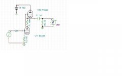
There you go. THD @ 1kHz @ 12VAC output is 0.34% into 1M ohm. THD is directly proportional to output, obviously. Bandwidth is about 1MHz. Gain is about 25dB.
Happy trails.
Happy trails.
Attachments
Last edited:
There you go. THD @ 1kHz @ 12VAC output is 0.34% into 1M ohm. THD is directly proportional to output, obviously. Bandwidth is about 1MHz. Gain is about 25dB.
Happy trails.
Is 12V out enough to drive a 6CU6?
Is 12V out enough to drive a 6CU6?
You tell me. What's your bias voltage on the 6CU6?
You tell me. What's your bias voltage on the 6CU6?
I'll have to measure it again but I want to say it was something like -20 to -20v...
What was the input signal to get that output ?There you go. THD @ 1kHz @ 12VAC output is 0.34% into 1M ohm. THD is directly proportional to output, obviously. Bandwidth is about 1MHz. Gain is about 25dB.
Happy trails.
The bottom line here is that there is no way that a SRPP is producing less output than a plain vanilla ECC82. If the ECC88 SRPP can't do it, your current situation means that the amp is clipping the input stage way before the output stage is overloaded.
Shoog
- Status
- Not open for further replies.
- Home
- Amplifiers
- Tubes / Valves
- 6CU6 Sweep Tube Monoblock Power Amp Build Log