Hi colleagues. I would like to discuss with you a new type of output stages.
Attachments
-
 ???????????0001.jpg276.5 KB · Views: 270
 -
 ???????????0002.jpg416.1 KB · Views: 250
 -
 ???????????0003.jpg319 KB · Views: 241
 -
 ???????????0004.jpg455.6 KB · Views: 222
 -
 ???????????? ??????????? ???? 2.jpg530 KB · Views: 244
 -
 ???????????? ??????????? ???? 3.jpg525.7 KB · Views: 202
 -
 ???????????? ??????????? ???? 4.jpg543.7 KB · Views: 177
 -
 ???????????? ??????????? ???? 5.jpg472 KB · Views: 154
So you put the crossovers right before the output buffer stage?
I see no benefit, and a few major drawbacks, to this. Perhaps you could explain the benefits or what I'm missing.
I see no benefit, and a few major drawbacks, to this. Perhaps you could explain the benefits or what I'm missing.
A standard solution will require three monoblock. Crossover. Three interconnect cable. In stereo mode, all multiply by two. Work will monoblock six equalization currents. Background appears. Advantage - The economic feasibility. Adjust the high voltage signal. Noise immunity. One input node. Lack of interconnect connectors. Common point for the entire system.
A standard solution will require three monoblock. Crossover. Three interconnect cable. In stereo mode, all multiply by two. Work will monoblock six equalization currents. Background appears. Advantage - The economic feasibility. Adjust the high voltage signal. Noise immunity. One input node. Lack of interconnect connectors. Common point for the entire system.
Disadvantages-
Crossover circuits will have to operate at very high signal voltage to drive buffer directly.
No global feedback to control distortion in output stage.
Another big disadvantage is that your buffers have relatively low, highly nonlinear input impedance. This will greatly affect the operation of your crossover circuits. 😉
This doesn't mean that you can't build an integrated tri-amp system. But you won't be the first. 😉
This doesn't mean that you can't build an integrated tri-amp system. But you won't be the first. 😉
Another big disadvantage is that your buffers have relatively low, highly nonlinear input impedance. This will greatly affect the operation of your crossover circuits. 😉
This doesn't mean that you can't build an integrated tri-amp system. But you won't be the first. 😉
Hello Fast Eddie D. All repeaters FET input and have a great input soprotivleniya.Osnovnoe dignity. Significant reduction in the audio path cascades.
Hello Fast Eddie D. All repeaters FET input and have a great input soprotivleniya.Osnovnoe dignity. Significant reduction in the audio path cascades.
I don't really understand what you're saying, but you're completely missing my point. FET inputs and "soprotivleniya" (whatever that is) have absolutely nothing to do with my point. My point is that you can't drive unity gain output buffers directly with the output of your filters. There's a whole lot that's wrong with that.
I don't really understand what you're saying, but you're completely missing my point. FET inputs and "soprotivleniya" (whatever that is) have absolutely nothing to do with my point. My point is that you can't drive unity gain output buffers directly with the output of your filters. There's a whole lot that's wrong with that.
Dear Fast Eddie D. The main purpose of the patent - eliminate extra stages. Exclude filters from the speaker. On the repeater input signal is applied to the chip PCM1794A. Read more here. http://www.diyaudio.com/forums/soli...el-p-n-p-channel-repeater-plated-input-3.html It turns out the shortest path three band in the world.
Hi,
The proof of the pudding would be manufacturers
beating a path to your door and offering you lots
of cash to exploit your wonderful design.
Sadly I don't see it. Its hard to fathom what it does
and it smacks of a solution looking for a problem
that simply does not exist, and a very naive
approach to active speaker design in general.
"Shortest path [whatever] in the world" means very little.
rgds, sreten.
Dear Fast Eddie D. The main purpose of the patent - eliminate extra stages. Exclude filters from the speaker. On the repeater input signal is applied to the chip PCM1794A. Read more here. http://www.diyaudio.com/forums/soli...el-p-n-p-channel-repeater-plated-input-3.html It turns out the shortest path three band in the world.
It's not going to work. I already explained why.
I would guess that I know way more than you do about this stuff, and I have never come up with anything to patent. Every single thing I've "invented" was already thought of and patented by somebody else.
Your idea is so obvious that if it actually did work, it would have been implemented a long time ago. We would all be talking about it right here already. That being said, if you do come up with something new and practical, then more power to you.
Of course, if you don't believe us, then go ahead and build it. You'll figure it out then. 😉
Your "repeater" circuit has some merit.
Still, it will not work in this application the way you intend for it to work. It is unity gain and requires a high voltage, low impedance source. It will interact with your filter circuits in ways that you won't like, I guarantee you.
But please don't think I'm trying to discourage you. Keep learning and keep trying to come up with new ideas.
Yeah
Keep it rollin'
🙂
I understand repeater as a mean to replicate the needed six channels and make them perform exactly the same !?!
Is that the goal ?
Keep it rollin'
🙂
I understand repeater as a mean to replicate the needed six channels and make them perform exactly the same !?!
Is that the goal ?
Last edited:
Your "repeater" circuit has some merit.
Still, it will not work in this application the way you intend for it to work. It is unity gain and requires a high voltage, low impedance source. It will interact with your filter circuits in ways that you won't like, I guarantee you.
But please don't think I'm trying to discourage you. Keep learning and keep trying to come up with new ideas.
Dear Colleagues. See how it can be done in the first clip. Listen to how it sounds, you can in the second clip, Sincerely. ??????????? ???????????? ???????????. ?????2 - YouTube ??????????? ???????????? ??????????? - YouTube
Dear Colleagues. See how it can be done in the first clip. Listen to how it sounds, you can in the second clip, Sincerely. ??????????? ???????????? ???????????. ?????2 - YouTube ??????????? ???????????? ??????????? - YouTube
What are we listening to?
How much power output do you get by driving a unity gain buffer directly from a filter circuit?
Do you understand the point I'm making? Or am I missing something?
It does look like you know how to build stuff.
Hi,
Your wasting you time trying to communicate.
If that was possible we'd have something sensible.
rgds, sreten.
Your wasting you time trying to communicate.
If that was possible we'd have something sensible.
rgds, sreten.
Hi,
Your wasting you time trying to communicate.
If that was possible we'd have something sensible.
rgds, sreten.
Somebody that has the skills to design and construct this device (even if it is fatally flawed) ought to be able to understand my point.
However, I suspect that you are correct. You can't blame me for trying to help.
The NPN-PNP hybrid output buffer i NOT a new invention, I have seen this some years ago from a fellow in Serbia. It can't possibly get a patent as it already has been published
The NPN-PNP hybrid output buffer i NOT a new invention, I have seen this some years ago from a fellow in Serbia. It can't possibly get a patent as it already has been published
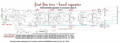
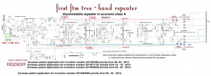
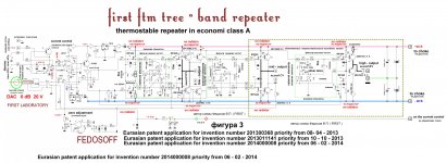
abstract
Output of the amplifier audio power
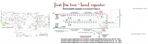
The invention relates to electronics and electrical engineering , namely the multi-band electronic amplifier , in particular, to the audio amplifier Hi-Fi, Hi End Class AB , V. achieved design simplification and improvement of energy and economic efficiency . The output stage comprises at least N filters with different amplitude- frequency characteristics , and N> 1 successive first and second circuits the voltage follower connected between the first and second DC power supply inputs . Pairing the first point and the second voltage follower outputs are cascade control inputs and first and second voltage follower to each of said pair through one of the filters is coupled between the bias resistor . Wherein the output stage further comprises :
- Power transformer with two windings , each of which is provided with a middle terminal . The ends of the first winding through the first rectifier unit connected to the first input supply and the second ends of the coil through the second rectifier unit connected to the second input supply. Average conclusions said windings connected to a common output power ;
- A third voltage follower , configured as a source follower having an input connected to the input of the output stage , and an output through the respective filters is connected to a control input of each of the first voltage follower ;
- The first current generator whose output through an appropriate filter is connected to the control input of each of the second voltage follower
- Status
- Not open for further replies.
- Home
- Amplifiers
- Solid State
- News. Three-band repeater with a crossover in the economy class A.