I have experienced failure of an LED (gone open circuit) in a meter backlight panel that consists of two identical modules fed from an 80 volt rail with the return into a conventional ring of two constant current sink (CCS). Also, several of the other LED's have very variable illumination suggesting that they have deteriorated. That said they have operated for several thousand hours, perhaps as many as 8 to 12 thousand at a guess.
Anyhow, I wondered how "transient proof" a CCS is in practice. Simulating the exact circuit shows up an anomaly, but of course the difference between the sim and the reality is that the 80 volt rail is across a few thousand uf of capacitance and so fast rise times of the supply are an impossibility.
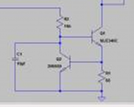
This is the circuit.

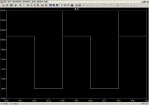
And this the LED current,

After replacing all the LED's I added a 33 ohm and 2.2uf cap across each module as a snubber. With the 33 ohm raised to 1meg for the sim you can see a huge current spike. It just got me wondering as to how safe LED's are when fed from a supply like this.
Anyhow, I wondered how "transient proof" a CCS is in practice. Simulating the exact circuit shows up an anomaly, but of course the difference between the sim and the reality is that the 80 volt rail is across a few thousand uf of capacitance and so fast rise times of the supply are an impossibility.
This is the circuit.
And this the LED current,
After replacing all the LED's I added a 33 ohm and 2.2uf cap across each module as a snubber. With the 33 ohm raised to 1meg for the sim you can see a huge current spike. It just got me wondering as to how safe LED's are when fed from a supply like this.
Kind of odd behaviour, like the CCS is too slow. I wonder if you used a current mirror the results might be better.
Like most other junctions, LEDs handle transients pretty well. I'd be more suspicious of crummy eBay LEDs or a thermal problem. They don't like to be hot and you've got quite a lot of 'em, probably in a small space. If transients really are the issue, I'd try putting a suitable MOV across 'em. I'd also have a limiting resister in series that's as large as practical because that will limit transient current, especially if you use a MOV and actually have it clamp something. It will also take some of the dissipation off the CCS.
I bet the problem is one of uneven voltage split across the series-connected parts. If gross enough, they will run at different temps and that will give differing illuminance.
Feeding the lot from a simple RC will deal with both start-up and transients cheaply and easily; make the R a 2-3w rated part and yes, it can take some for the disspation off the CCS.
Or you might bin the CCS and just use two medium-power resistors with the centre joint strapped to 0v by the cap (strap to the 80v rail, for a 'sink'.) With 20 LEDs to light at say 2mA you'll be looking to drop ~40V, at 2mA say - two 10Kohm, 2W in series will do nicely. Cap can then be quite small, 10uF or a bit more, limiting transients to below 1.5Hz. The poor mans' CCS - compact, cheap and very robust!
Last edited:
Hi,
Hello molly long time do not talk to you. As you know I fix everything using a micro but this time my suggestion would be what about using a light sensor that read one of the led light and control the current mirror. It will prevent the LED's to light bright when the power it is applied. Here in my town they replaced the incandescent traffic lights with LED's and now you can see them with some LED's rows off. Maybe they have the same problem you have,
Hello molly long time do not talk to you. As you know I fix everything using a micro but this time my suggestion would be what about using a light sensor that read one of the led light and control the current mirror. It will prevent the LED's to light bright when the power it is applied. Here in my town they replaced the incandescent traffic lights with LED's and now you can see them with some LED's rows off. Maybe they have the same problem you have,
Hi,
Hello molly long time do not talk to you. As you know I fix everything using a micro but this time my suggestion would be what about using a light sensor that read one of the led light and control the current mirror. It will prevent the LED's to light bright when the power it is applied. Here in my town they replaced the incandescent traffic lights with LED's and now you can see them with some LED's rows off. Maybe they have the same problem you have,
Optical feedback! Very cool idea.
With CCS and everything in series, obviously the current through each device is the same. That seems like what you want, but I have to wonder, is there any good reason to match them so the forward voltage is the same as well?
Optical feedback! Very cool idea.
With CCS and everything in series, obviously the current through each device is the same. That seems like what you want, but I have to wonder, is there any good reason to match them so the forward voltage is the same as well?
Light output is proportional to current...the reason not to drive LED's with voltage.
LED's voltage drop at current is temperature sensitive...another reason not to drive LED's with voltage.
If you want an easy feedback of light intensity look at an OPT101...very easy to use.
Thanks for all your thoughts 🙂
I don't know, its an interesting idea though.
As it all stands a redesign wouldn't really be possible as the CCS is incorporated into a PCB with lots of other stuff on it.
Tbh, I do kind of suspect the LED's weren't that great to begin with although they were from a recognised supplier (CPC, part of Farnell). I remember at least one being dead at the time of fitting. Adding the 2.2uf cap and 33 ohm stops the transient spike in simulation, so that is what I ended up doing on the boards.
I have replaced them all with these high brightness types,
L-7104SURC-E - KINGBRIGHT - LED, 3MM, 1300MCD, RED, CLEAR | CPC
That would certainly remove any possibility of transient damage. The reason I didn't do anything like that at the time (don't laugh) was to ensure a good "user impression" of the backlighting. It comes on smartly on power up and goes out virtually instantly on power off thanks to the series zeners.... no fading into the distance as the rails slowly collapse. Why do we make life difficult for ourselves 😀
We've started to see LED streetlighting in some areas. It doesn't seem as effective as the orangey coloured sodium ? lights, particularly when the ground is damp.
Kind of odd behaviour, like the CCS is too slow. I wonder if you used a current mirror the results might be better.
I don't know, its an interesting idea though.
As it all stands a redesign wouldn't really be possible as the CCS is incorporated into a PCB with lots of other stuff on it.
Like most other junctions, LEDs handle transients pretty well. I'd be more suspicious of crummy eBay LEDs or a thermal problem. They don't like to be hot and you've got quite a lot of 'em, probably in a small space. If transients really are the issue, I'd try putting a suitable MOV across 'em. I'd also have a limiting resister in series that's as large as practical because that will limit transient current, especially if you use a MOV and actually have it clamp something. It will also take some of the dissipation off the CCS.
Tbh, I do kind of suspect the LED's weren't that great to begin with although they were from a recognised supplier (CPC, part of Farnell). I remember at least one being dead at the time of fitting. Adding the 2.2uf cap and 33 ohm stops the transient spike in simulation, so that is what I ended up doing on the boards.
I have replaced them all with these high brightness types,
L-7104SURC-E - KINGBRIGHT - LED, 3MM, 1300MCD, RED, CLEAR | CPC
I bet the problem is one of uneven voltage split across the series-connected parts. If gross enough, they will run at different temps and that will give differing illuminance.
Feeding the lot from a simple RC will deal with both start-up and transients cheaply and easily; make the R a 2-3w rated part and yes, it can take some for the disspation off the CCS.
Or you might bin the CCS and just use two medium-power resistors with the centre joint strapped to 0v by the cap (strap to the 80v rail, for a 'sink'.) With 20 LEDs to light at say 2mA you'll be looking to drop ~40V, at 2mA say - two 10Kohm, 2W in series will do nicely. Cap can then be quite small, 10uF or a bit more, limiting transients to below 1.5Hz. The poor mans' CCS - compact, cheap and very robust!
That would certainly remove any possibility of transient damage. The reason I didn't do anything like that at the time (don't laugh) was to ensure a good "user impression" of the backlighting. It comes on smartly on power up and goes out virtually instantly on power off thanks to the series zeners.... no fading into the distance as the rails slowly collapse. Why do we make life difficult for ourselves 😀
Hi,
Hello molly long time do not talk to you. As you know I fix everything using a micro but this time my suggestion would be what about using a light sensor that read one of the led light and control the current mirror. It will prevent the LED's to light bright when the power it is applied. Here in my town they replaced the incandescent traffic lights with LED's and now you can see them with some LED's rows off. Maybe they have the same problem you have,
We've started to see LED streetlighting in some areas. It doesn't seem as effective as the orangey coloured sodium ? lights, particularly when the ground is damp.
Capacitor "C1" in the current source makes me queasy. The 2-NPN source is a tightly coupled negative feedback loop, and C1 loosens the coupling at high frequencies*; I worry that this may introduce lots of gain-peaking, giving a propensity to oscillate. The peaks of the oscillation may suck far more current through the LED string, than reliability engineers or datasheet sticklers would prefer.
If that were my circuit, and if I had that problem, I think I'd start with a careful AC analysis of the open-loop gain and phase in this little "feedback control system". I'd ask myself, what happens when I schmeer (a) NPN beta; (b) NPN Early voltage; (c) capacitor C1's value, across a wide range. Then I'd ask LTSPICE the same questions 😉
*until ESR and ESL begin to dominate 1/(2*pi*f*C)
{sorry for the low res picture, the original in post#1 was very small, and I zoomed it 600%}
Attachments
Hi,
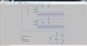
Attached it is a schematic of a simple idea to prevent the burned out of the LED's. I think the problem it is the high voltage of 80 volt that will caused a high inrush current at the turn ON of the LED's. What I proposed it is to add another resistor to lower the voltage at turn ON and delay it to allow the LED's to turn ON. Once the LED's are ON then the resistor will be bypass by transistor Q1. This will prevent the inrush over current and the high voltage at the turn ON. The idea it is that once all LED's are ON it will have a voltage drop of 1.7 volts each x 20 LED"S = 34 volt and R1 will dropped 40 volt that will balance the voltage of 80 volts. You may have to adjust the R1 to for the LED's brightness. Sorry but I am a lousy technical writer. Hoped the schematic explained it better.
Attached it is a schematic of a simple idea to prevent the burned out of the LED's. I think the problem it is the high voltage of 80 volt that will caused a high inrush current at the turn ON of the LED's. What I proposed it is to add another resistor to lower the voltage at turn ON and delay it to allow the LED's to turn ON. Once the LED's are ON then the resistor will be bypass by transistor Q1. This will prevent the inrush over current and the high voltage at the turn ON. The idea it is that once all LED's are ON it will have a voltage drop of 1.7 volts each x 20 LED"S = 34 volt and R1 will dropped 40 volt that will balance the voltage of 80 volts. You may have to adjust the R1 to for the LED's brightness. Sorry but I am a lousy technical writer. Hoped the schematic explained it better.
Attachments
Capacitor "C1" in the current source makes me queasy. The 2-NPN source is a tightly coupled negative feedback loop, and C1 loosens the coupling at high frequencies*; I worry that this may introduce lots of gain-peaking, giving a propensity to oscillate. The peaks of the oscillation may suck far more current through the LED string, than reliability engineers or datasheet sticklers would prefer.
If that were my circuit, and if I had that problem, I think I'd start with a careful AC analysis of the open-loop gain and phase in this little "feedback control system". I'd ask myself, what happens when I schmeer (a) NPN beta; (b) NPN Early voltage; (c) capacitor C1's value, across a wide range. Then I'd ask LTSPICE the same questions 😉
*until ESR and ESL begin to dominate 1/(2*pi*f*C)
{sorry for the low res picture, the original in post#1 was very small, and I zoomed it 600%}
Thanks Mark. Removing the cap in simulation certainly reduces the amplitude of the spike but doesn't by any means eliminate it. In practice of course there is the effect of the rail capacitance that severely limits rise and fall times... and it was really any off the wall transients I was wondering about such as when the amp is switched on and switched off... those kind of events and whether anything might couple through the into the LED's. I set the sim to have fast rise and fall times and its under these conditions the spike shows.
I'm reasonably happy at the moment with the cap and resistive snubbers in place but if I designed another similar circuit I'd perhaps do things differently.
Here is a better picture hopefully.
Attachments
Hi,
Attached it is a schematic of a simple idea to prevent the burned out of the LED's. I think the problem it is the high voltage of 80 volt that will caused a high inrush current at the turn ON of the LED's. What I proposed it is to add another resistor to lower the voltage at turn ON and delay it to allow the LED's to turn ON. Once the LED's are ON then the resistor will be bypass by transistor Q1. This will prevent the inrush over current and the high voltage at the turn ON. The idea it is that once all LED's are ON it will have a voltage drop of 1.7 volts each x 20 LED"S = 34 volt and R1 will dropped 40 volt that will balance the voltage of 80 volts. You may have to adjust the R1 to for the LED's brightness. Sorry but I am a lousy technical writer. Hoped the schematic explained it better.
Thanks tauro, appreciate it. A picture is worth a thousand words 🙂
Sometimes you just can't beat a good old resistor solution. No transients there.
Browsing the digikey or mouser catalogue you will discover a variety of dedicated LED drivers, both linear and switched. Some are designed for specific types of LEDs and operating conditions. I suggest you have look at these.
Also, LEDs for illumination or back-lighting are available in sorted batches or bins, so you do not get variation in colour or brightness from one to the next.
Also, LEDs for illumination or back-lighting are available in sorted batches or bins, so you do not get variation in colour or brightness from one to the next.

- Status
- Not open for further replies.
- Home
- Amplifiers
- Power Supplies
- Thoughts on running LED's from high voltage into a constant current sink.