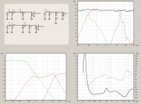
It looks like a 2nd order on the mid driver and a first order on the HF- there are only 3 components on my passives. The only one with a readable value is on the MF- a 3.3uf cap and unknown value coil.
Remember that if you go this route that the HF and MF will be out of polarity.
I am guessing that the HF will need to reverse polarity.
Try this 😉
Hi Jzagaja,
Do you have values for the components (R,L,C) ?
Best,
Thanks, PM sent.Won't you try find values yourself? ;-) Send me PM.
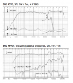
On the BMS 4590P is a filter attached. The BMS 4590 comes without.
ah, I wondered about the 'P'
is it a good driver ?
The 4590 is a good co-ax mid/HF driver, but the "P" crossover is not really up to the task of providing a smooth frequency response in the crossover region, which probably requires DSP to really get right, there is a lot going on inside that throat.ah, I wondered about the 'P'
is it a good driver ?
And to "get it right", (as stated earlier in this zombie thread), would be horn dependent.
Attachments
no, I would not buy the P version with xo
btw, any chance to find a cut view of this driver ?
I don't think this ferrite version is overly expencive
and maybe if it can be crossed low enough ...
but shoot ... I'm just now reminded it still cost more than a fancy 1.5" I usually consider too expencive
btw, any chance to find a cut view of this driver ?
I don't think this ferrite version is overly expencive
and maybe if it can be crossed low enough ...
but shoot ... I'm just now reminded it still cost more than a fancy 1.5" I usually consider too expencive
Cut sheet or cutaway view are easy to find.btw, any chance to find a cut view of this driver ?
You can see that the VHF leads the HF (has a shorter path length) which can be corrected with DSP, but is hard to get "just right" passively.
Attachments

really ?
no, I would not buy the P version with xo
btw, any chance to find a cut view of this driver ?
Found your high-end plastic compression driver as you declared ?
plastic ? ... wow 😀
well, plastic or not, I can declare that I'm looking for the big BMS 1.4" and 1.5" neo mid drivers
but that is a different matter/topic
well, plastic or not, I can declare that I'm looking for the big BMS 1.4" and 1.5" neo mid drivers
but that is a different matter/topic
Cut sheet or cutaway view are easy to find.
You can see that the VHF leads the HF (has a shorter path length) which can be corrected with DSP, but is hard to get "just right" passively.
OK, there is quite a bit of mis-information here. In the attachment shown, the picture is from old BMS literature, and is a 4590, but the illustration is quite obviously not. Further more, the illustration is not one I have seen before, but seems to be to show how the driver works, and is not a photograph. I think that if everyone here understands that the sound from both diaphragms needs to meet at the same time, then the good people at BMS understand the same. The driver has been designed so that the sound meets at the same time. Actually there is a small bit of smearing, because the sound from the outside of the diaphram (mid) has further to go than the inside, but at 6khz, the wavelength is about 2", so both that and the arrival of the HF diaphragm are within 1/4 wavelength. (We know from watching how a unity or synergy speaker works that having different motors within 1/4 wavelength apart is the goal.)
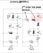
To the crossover. It is a very simple design. Ist order one direction, 2nd order the other. Two caps and one inductor. It is very good at what it is designed to do. Which is combine the signals, so the sensitivity of both motors is the same at the crossover point. So that the user can use one amp channel to drive both motors. What it does not do is provide any kind of EQing, or impedance matching for the driver in the horn. The user will still have to approach this as if they were using any single motor driver. And provide the needed processing to get a flat frequency response. (Also, if you read much Danley, the phase response in a horn will get better as your response flattens.)
To repeat, the BMS crossover is good for making the driver behave as a single unit. It is not designed to do any EQing, nor does it have any zobel networks.
If you are going to do an intense passive design for EQing, you will already so far in that you can do your own crossovering also.
If you are using active EQ before the amp, the simple BMS crossover will be a good solution to use the dual motor driver with only one amp channel.
It would have been beneficial if BMS would have designed the driver so that HF lagged behind the MF. This makes passive crossover work so much easier because of their phase behavior. This is why the compression driver is always behind the mids, and the mids are behind the woofers in a Synergy horn. The goal for the BMS driver should have not been to get the two drivers to arrive at the same time, but to make it possible for the competent designer to make it happen within their crossover design. See below thread for the type of principles used in optimizing crossovers and distance offsets of HF and MF drivers.
http://www.diyaudio.com/forums/mult...sover-high-efficiency-loudspeaker-system.html
http://www.diyaudio.com/forums/mult...sover-high-efficiency-loudspeaker-system.html
This is quite a different discussion that you link. There, they are trying to optimize a woofer, front load, to a horn loaded compression driver. Here, we have two units that are being impedance loaded to a single horn. No need to correct for group delay.
The same principles apply. Drivers don't know whether they are a woofer, mid, compression driver, or a coaxial driver. For best coherence requires phase alignment (elimination of group delay). All low pass filters cause group delay. To get the two drive units back into "time" with each other there needs to be a physical offset. If the HF driver is at the same distance as the MF driver you will never have perfect coherence. Example below using the quasi-optimal 3rd order crossover which allows for the least amount of physical offset.
3rd order Butterworth Low Pass, -3dB @ Fx*0.87 (+)
3rd order Butterworth High Pass, -3dB @ Fx*1.15 (-)
Offset = 0.22*c/Fx
With a 6.3KHz crossover we would want the HF driver to be 1.196cm behind the MF driver. The low pass filter for the MF driver would be 5.48KHz and the HF high pass filter would be 7.24KHz.
This works with pro sound coaxial drivers too. Its just a matter of scaling for the frequency requirements. There is a lot more to passive filter design than amplitude summation at the crossover point. Of course you can avoid all this by simply using DSP.
Last edited:
The same principles apply......
Of course you can avoid all this by simply using DSP.
and the same principles apply ... 😀
3rd order Butterworth Low Pass, -3dB @ Fx*0.87 (+)
3rd order Butterworth High Pass, -3dB @ Fx*1.15 (-)
Offset = 0.22*c/Fx
With a 6.3KHz crossover we would want the HF driver to be 1.196cm behind the MF driver. The low pass filter for the MF driver would be 5.48KHz and the HF high pass filter would be 7.24KHz.
A) What is the offset with a 1st order?
B) at 1.1CM, this is about 1/8th wavelength. Not a very big issue, when all of the other concerns with passive are taken into consideration.
- Status
- Not open for further replies.
- Home
- Loudspeakers
- Multi-Way
- BMS 4590P filter