
Hello guys
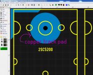
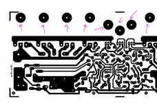
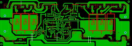
make sure if you are using the file for "etching" make all the holes smaller so you will have enough material for soldering usually 0.60 mm hole diameter for all is ok so then you can chose 0.90 mm for diodes and 1 mm for the MJE15032 etc, the main power transistors are about 1.48 mm round it up to 1.50 mm diameter hole, the rest caps are usually 0.80 mm some are tickers than others 🙂 also enlarge the hole pads copper area for the main transistors that help to align them sorry I forgot select only C2 do not enable C1
Regards
Juan
Attachments
Last edited:
Hello Juan .
Is it possible you post pdf? I can't open this "lay" file.
Best regards.
Thimios
Is it possible you post pdf? I can't open this "lay" file.
Best regards.
Thimios
Sure dear thimios, let me install PDF creator then I will send you the PDF files no problem man 🙂 I will made all holes smaller for ya so you don't have to do it give me a moment please 🙂
Regards
Juan
Regards
Juan
Juan,Sure dear thimios, let me install PDF creator then I will send you the PDF files no problem man 🙂 I will made all holes smaller for ya so you don't have to do it give me a moment please 🙂
Regards
Juan
please send me too regads fhoenix
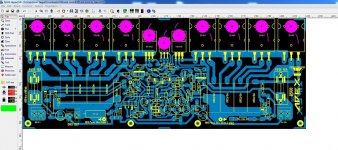
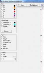
Ok I'm back, I will leave here different sizes because in the past I use think that layout from a PDF file will be just fine and the dimensions are correct 🙄, I found out that after the files is transfer to a "virtual image PDF the size might be a bit smaller" but if you are using a "real printer" size will be accurate using 1:1 and it will give you and accurate size of the layout if you are using the straight out of the software PC to printer it will be good very good 😀.
God knows how many printings I did to test it out on PDF files 😛, even if I chose A4 or other format it will always change the size of the layout, for that reason what I do is I print different sizes and then I compare them using MJL3281A leads to see if they align correctly, is not 100% accurate but it works, if you are to print those sizes use "draft only" to almost grey to safe ink or cartridge life,
when you find out what size work best for you then you can print the final one you are going to use for the etching, here are the files 🙂 , I think 130 size is way too big but I will leave it here any way 😀
Regards
Juan
Attachments
Last edited:
Juan,
please send me too regads fhoenix
Sure man I do not mind at all 😀
Regards
Juan
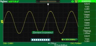
CONGRATULATION.SMD - version,3 pairs, stabilized +-50V SMPS, 32V RMS, 4 Ohm. good sound🙂
Which format is this lay file?
Regards.
Thimios.
SL-6. In the ZIP file SL5.Which format is this lay file?
Attachments
An externally hosted image should be here but it was not working when we last tested it.
An externally hosted image should be here but it was not working when we last tested it.


M.R APEX
B500 AMPLIFIER
WHY IN THE CERSUIT R25-R24 = 2.2K 2W / IN PCB R25-R24 = 4.7K 2W
AND THE DIOD IN THE CERCIT D = IN4007 / IN PCB D = IN4004
What is the correct value of these pieces ?
BEST REGARD
B500 AMPLIFIER
WHY IN THE CERSUIT R25-R24 = 2.2K 2W / IN PCB R25-R24 = 4.7K 2W
AND THE DIOD IN THE CERCIT D = IN4007 / IN PCB D = IN4004
What is the correct value of these pieces ?
BEST REGARD
Last edited:
Regards
Sorry that I could not speak English well. Can you share me the input circuit unbalance + balance in 1pcb for apex b500tef thanx
please..
Sorry that I could not speak English well. Can you share me the input circuit unbalance + balance in 1pcb for apex b500tef thanx
please..
Fans of B600 is still small, compared to the B500. I was thinking, why is that? well... I know B600 better than B500. so.. why fans of B600 still small ?
Fans of B600 is still small, compared to the B500. I was thinking, why is that? well... I know B600 better than B500. so.. why fans of B600 still small ?
I think because B500 was born earlier than B600. B500 schematics was created a few years ago, and B600 schematics was created and shared by Mr. Mile just a few months ago. And we know there is some people in our country who gets the schematics of B600 from this forum won't share the layout for us here. I don't know why he/she won't share. I think because of that the fans of B600 is less than B500 in this forum.
- Home
- Amplifiers
- Solid State
- 500W PA amplifier with Limiter