Well, this one puzzles me, despite my experience in the field.... On the left channel there is a randomly appearing flicker noise sometimes. It is not from the opamp, it is in a socket and replaced already for an LM49860, same story. I also replaced the input diff. pair on the poweramp section (same types), but the noise keeps coming back. I cheked it with a scope, but with the complexity of the circuit it is difficult to pin down the source of the noise. Anyone with experience on this problem?
Attachments
Difficult. A scope check will only confirm what you can hear, it won't pin it down unless its a problem with the applied input.
Looking at the circuit I would look toward the 68 and 27pf caps and the two pre-driver transistors. The 2n2 input cap might be worth a look. Also D203 is it, the 4148 bypassed by a 220uf. Beyond that just swap all the 4148's for new and then (as now) its a case of substituting parts.
I would say that dripping (not squirting) freezer spray can be very very useful in these cases.
A tough one I'm afraid.
Well, this one puzzles me, despite my experience in the field.... On the left channel there is a randomly appearing flicker noise sometimes. It is not from the opamp, it is in a socket and replaced already for an LM49860, same story. I also replaced the input diff. pair on the poweramp section (same types), but the noise keeps coming back. I cheked it with a scope, but with the complexity of the circuit it is difficult to pin down the source of the noise. Anyone with experience on this problem?
In the meantime, I had many devices of this model. Schematic diagram has a very bad resolution, so I can't read the part-number of the parts.
Follow is to do befor you start any troubleshooting:
1) removing the op-amp and MUTE-jFETs in front of OP-Amp (include op-amp the gain factor is too large - approximately 250-500)
2) introduce of a serial capacitor for the signal pad in front of and behind the volume control (the cap behind the volume control goes to the power amp input (R201/R202 so as R302/303)
3) desolder and dissassembly the volume control for polish the silver slide
4) replacing of all capacitors which remain in use.
Then you can start the actually trouble shooting.
If the flicker noise is still present, you must investigate the front-end (i. e. LTP and VAS) so as the output buffer from the power amp section independently (therefore you must connect the NFB-loop to the VAS-output and for test the output buffer you need an additional Vbe multiplier).
After narrowing down the fault to a particular section you can substituting the components from the faulty channel to the working channel (and vice versa), until the error on the working channel appears.
Then you have definitely found the faulty component.
Good luck with your search.
Last edited:
Thank you very much for your valuable ideas... I will try the things you suggested, hoping for the best.
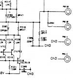
One more thing caught my attention on the power amp section, and it seems strange... It is common on many output stages to use an output Zobel, but here the values do not make sense. You can see them in the middle section of the (rather bad quality) picture. There is a 220nF going to the ground directly, then a 330nF in series with a 0,47 ohm resistor. Which means that the output of the amp is practically shunted with a 0.55uF capacitor. Does it make sense to anyone, and if yes, why it is used? (the commonly used values are around 100nF in series with a few ohms)
Attachments
Makes me wonder, many schematics I see have serious "drafting" errors.
Always wanted to see their amp schematic. Totally conventional in architecture. I expect their execution is well done.
Always wanted to see their amp schematic. Totally conventional in architecture. I expect their execution is well done.
Not big on swapping parts.I know feedback circuits can be a real pain to debug, but swapping tends to lead to more failures.
Finger test? Are all the parts on R and L about the same temp?
Tap test. Tap each part with a pencil.See if any glitches happen.
Magnifying glass test. Look for cold solder joints.
Don't forget to look all the way back to the PS.
Finger test? Are all the parts on R and L about the same temp?
Tap test. Tap each part with a pencil.See if any glitches happen.
Magnifying glass test. Look for cold solder joints.
Don't forget to look all the way back to the PS.
The resistor is a 0.47 ohm 2W square ceramic type.
Thanks.
I was just thinking hazily on what the dissipation might be under full power testing at say 20kHz but at 2 watt its not a problem.
Dunno is the honest answer... its a very unusual set up for sure.
Temperature test OK, both channels , all parts same temp. Io OK (64/66mA), DC offset within 10 mV, Scope check OK, no oscillation, no noise (except of course that ominous left channel flicker), no distortion, with a 15 ohm 20W power resistor the clipping is fully symmetrical. If anyone interested in the schematic (it has one of the best integrated amp MM/MC phono stage I've ever seen and heard....), send me a PM.
The same weird 330 nF/0R47 output Zobel network is used on Linn Kloud - and probably other Linn models too. Most designers seem to find the standard 100 nF/5-10R fits all sizes.
The real oddball is C386, that 220 nF cap, direct to ground. What were they thinking - a sharper knee filter?
The real oddball is C386, that 220 nF cap, direct to ground. What were they thinking - a sharper knee filter?
The early versions of LK2 (not LK2-80) use only the 100nF cap (EVOX).The same weird 330 nF/0R47 output Zobel network is used on Linn Kloud - and probably other Linn models too. Most designers seem to find the standard 100 nF/5-10R fits all sizes.
The real oddball is C386, that 220 nF cap, direct to ground. What were they thinking - a sharper knee filter?
But it is to observe, that a Zobel network was later supplemented (330nF/4R7 - low induction, i.e. not wire wound version) in free wiring.
Schematic of the Klout (not Kloud) is by post 51+52 under
http://www.diyaudio.com/forums/solid-state/106226-tweaking-classic-linn-lk1-lk2-lk280-6.html
I also don't understand the choice of only one capacitor without resistor (instead usual zobel network) at the output to GND in the first version, but OTOH - I don't observe any trouble regarded this until this day. Therefore this approach is probably to consider in order to the whole compensation for best phase margin (please note: instead the usual used one capacitor solution for "C-dom" here are three devices in use: C202/203/R207 - exact like at LK-2 and other models from this time - check out also the picture by post # 32 about
http://www.diyaudio.com/forums/solid-state/106226-tweaking-classic-linn-lk1-lk2-lk280-4.html).
Last edited:
Good to know, as I was confused by your earlier posted schematic: http://www.diyaudio.com/forums/atta...c-linn-lk1-lk2-lk280-c_tmp_linn-kloud_ckt.pdf......Schematic of the Klout (not Kloud) is by post 51+52 under
http://www.diyaudio.com/forums/solid-state/106226-tweaking-classic-linn-lk1-lk2-lk280-6.html......
Anyway, your efforts of supplementing and posting the scarce amount of information on Linn amplifiers is much appreciated.
I had a similar fault with my Intek with a flicker noise and found the 220uf feedback capacitor (C204 C304) on the LTP was causing the problem.
Yess! Thanks a lot to msdin!!! That good ol' 220u Black Gate..... Problem solved (Replaced them with 16V Silmics, they even sound a tad better.
Glad to help.
Not sure if you are use a turntable but the phono-stage also benefits if you change out the old Black Gate caps and replace them with Elan Cerafine and Silmic capacitor.
Not sure if you are use a turntable but the phono-stage also benefits if you change out the old Black Gate caps and replace them with Elan Cerafine and Silmic capacitor.
Because I replace all caps before I start troubleshooting, I haven't discover this.Yess! Thanks a lot to msdin!!! That good ol' 220u Black Gate..... Problem solved (Replaced them with 16V Silmics, they even sound a tad better.
Here a picture of an opened device:
http://www.avx.hu/forum/uploads/post-20-1240299787.jpg
For all new caps I use always 63V versions in case of voltages <+/-40VDC and 100V versions in case of voltages <-/+70VDC
Just some thing I've noticed is that the LK100 power amp is almost the same as the Intek.
Linn LK-100 - pink fish media
Something in the pre-amp is holding the sound quality of this amp back.
If you get the opportunity try a different pre-amp, I've used it with a Naim NAC82 (Now cloned) and it sound very good.
You will of course need to remove two link on the pcb.
Linn LK-100 - pink fish media
Something in the pre-amp is holding the sound quality of this amp back.
If you get the opportunity try a different pre-amp, I've used it with a Naim NAC82 (Now cloned) and it sound very good.
You will of course need to remove two link on the pcb.
- Status
- Not open for further replies.
- Home
- Amplifiers
- Solid State
- Linn Intek noisy channel