If you are not interested in discussing measurement and listening results for room correction, and the correlation thereof, why bother posting your question then?
All the best, Mitch
I am interested in that discussion but I don't think that casual listening tests have much value. I've tricked myself too many times thinking that critical listening alone would be enough. It's not. We can't overcome subconscious biases. It's simply impossible.
Two examples:
1. The McGurk Effect | Auditory Neuroscience
2. Which line between the arrows is longer? Measure them.
We can't overcome biases even if we know they exist.
Attachments
I don't think that casual listening tests have much value. I've tricked myself too many times thinking that critical listening alone would be enough. It's not. We can't overcome subconscious biases. It's simply impossible.
so true
🙄
I am interested in that discussion but I don't think that casual listening tests have much value. I've tricked myself too many times thinking that critical listening alone would be enough. It's not. We can't overcome subconscious biases. It's simply impossible.
We can't overcome biases even if we know they exist.
All too aware of this as a 10 year ex recording/mixing engineer. But I am not talking about casual listening tests.
If you checked out the links I provided, you would see I am talking about properly set up and executed ABX tests: http://www.hydrogenaudio.org/forums/index.php?showtopic=16295
The ABX tests I design are intended to be repeatable by anyone as the tools and procedures for each test are listed, along with both measurements and listening results, including the test files and difference files.
These tests are designed to determine what we can and cannot hear on an individual basis, like the one I already linked to bit perfect audibility testing, or do digital audio file formats sound the same or different, do digital audio music players sound the same or different or can one hear the difference between 16/44 versus 24/192. These are not casual listening tests, but complete ABX tests with measurements correlated to what we hear.
My point is/was why not setup a proper ABX test of listening to minphase and linphase correction filters to determine what your preference is. Then correlate your results with others here on the forum using the same AB or ABX test. Otherwise, how do you expect to get answers to your questions?
Best regards, Mitch
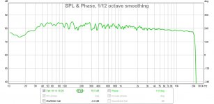
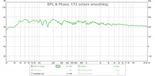
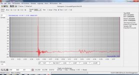
I am not a REW guru as I spend most of my time using Acourate, but here are a couple of charts using the default window size, 1/12 octave smoothing, and measured at the LP some 10 feet away. I fed the REW signal into the ASIO digital line input of JRiver with the Convolution engine and FIR filter engaged.
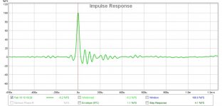
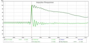
Frequency response is similar to what jtalden has. Virtually textbook linear phase impulse response and step response with no preringing.
Good luck Markus.
Best, Mitch
Frequency response is similar to what jtalden has. Virtually textbook linear phase impulse response and step response with no preringing.
Good luck Markus.
Best, Mitch
Attachments
Room Correction with PEQ
You guys are over complicating a simple matter.
1) Get a PEQ
2) Turn some knobs
3) Start enjoying the music

An externally hosted image should be here but it was not working when we last tested it.
We're talking about steady state in-room responses. Every response within the listening area represents a linear system. If there are minimum phase regions that are the same for each and every system (look at the excess group delay) then all system responses can be improved with a single filter.
Are you unaware or don't you believe Schroeder's fundamental work in this area showing that the response that you are talking about is a random variable? MP or not, is is not a stationary measure. Move an inch and it changes. Wait awhile for the temperature to change a degree or so and it changes. You are going to EQ that? Good luck!
Move an inch and it changes.
No, there are frequency regions where it doesn't change that much. Depends how close measured points are. But even when they differ one can get all points closer to flat. Here are some examples: http://mehlau.net/audio/multisub_multeq_xt32/
Frequency response is similar to what jtalden has. Virtually textbook linear phase impulse response and step response with no preringing.
Best, Mitch
Mitch,
Are those supposed to be acoustic measurements? Why is there a DC response?
No, there are frequency regions where it doesn't change that much. Depends how close measured points are. But even when they differ one can get all points closer to flat. Here are some examples: Minimizing seat-to-seat variance with two subwoofers
When did the discussion all of a sudden become restricted to LFs?
When did the discussion all of a sudden become restricted to LFs?
It didn't but in acoustically small rooms the properties I've been talking about are found at lower frequencies and not at high frequencies. This doesn't falsify what I've said though:
"If there are minimum phase regions that are the same for each and every system (look at the excess group delay) then all system responses can be improved with a single filter."
Maybe it doesn't falsify it at HFs, but it does make it meaningless. Just sounds like you trying to win at argument at all costs.
Mitch,
Are those supposed to be acoustic measurements? Why is there a DC response?
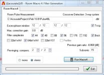
Earl, oops forgot the subsonic filter...
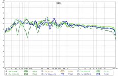
Just for fun and not too scientific, I took 6 measurements with REW (feeding through JRiver Convolver with Acourate generated FIR filter) while moving the mic in 1.5 ft increments from the LP to the left and right and then the same again, but 2 feet back.
This is to show that the FR (1/6 oct smoothing) is pretty good across a 6ft couch area, and whether leaning forward or sitting back 2 feet. Mic height remained constant at ear height.
I only measured the right speaker, and the response is at it's worst when the mic is furthest away from the speaker (i.e. left 3 feet and back 2 feet from the central LP).
Even still, pretty smooth across a 6 foot couch area...
Attachments
Last edited:
That impulse response does not look like any other loudspeaker impulse response that I have ever seen. I really have to question your data - it doesn't pass the credibility test.
That impulse response does not look like any other loudspeaker impulse response that I have ever seen. I really have to question your data - it doesn't pass the credibility test.
?? I am not an REW expert, so maybe I have it wrong. Here is the REW mdat file: https://westcoastdpe.blob.core.windows.net/diyaudio/Feb 16 Center.mdat Perhaps you can point out my error?
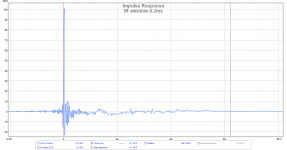
Looks like you have a major reflection just beyond 6.2ms
Attachments
Last edited:
?? I am not an REW expert, so maybe I have it wrong. Here is the REW mdat file: https://westcoastdpe.blob.core.windows.net/diyaudio/Feb 16 Center.mdat Perhaps you can point out my error?
I don't know REW either, but I do know that no acoustic impulse response can have a DC signal filter or no filter. Yours had a DC response, hence they could not have been acoustic signals. You add in a "subsonic" filter and the DC response fell, but the signals still looked like they had very good LF response - i.e. a very slow step response fall and a single impulse instead of a doublet. The "ideal" loudspeaker impulse response has too be a doublet, not a single impulse, because acoustics does not allow DC. So something in your data is wrong, somewhere. None of the impulse responses that I get on my systems ever have a single peak, there are always two - one positive and one negative. When you don't see that something is wrong.
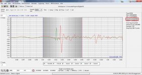
But they are acoustic signals. Attached is an impulse response of the right speaker before "digital" correction. You can clearly see the doublet. One can see the measured doublet's on each of my individual speakers in my 3-way system in this article: Computer Audiophile - Advanced Acourate Digital XO Time Alignment Driver Linearization Walkthrough
I have attached the doublet of my midrange CD driver in red. Note in green is the midrange digital XO - it's linear phase. This screen is in process of time aligning the midrange to the midrange digital XO point from the lined article.
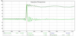
Also attached is a screen where I have added a subsonic filter at 15 Hz before generating the digital correction filters and measured again at the LP.
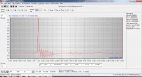
The last screen is a test convolution (and a zoomed test convolution) which shows what the simulated response is going to be. It is linear phase. The simulated pulse response correlates quite closely with the REW measured impulse response.
I am pretty sure nothing is wrong with my data.
I have attached the doublet of my midrange CD driver in red. Note in green is the midrange digital XO - it's linear phase. This screen is in process of time aligning the midrange to the midrange digital XO point from the lined article.
Also attached is a screen where I have added a subsonic filter at 15 Hz before generating the digital correction filters and measured again at the LP.
The last screen is a test convolution (and a zoomed test convolution) which shows what the simulated response is going to be. It is linear phase. The simulated pulse response correlates quite closely with the REW measured impulse response.
I am pretty sure nothing is wrong with my data.
Attachments

Last edited:
Looks like you have a major reflection just beyond 6.2ms
Yes, it is better to look at the ETC to see that it is about -15dB down from the main signal. Ideally it would be -20 dB or better. It is the only major reflection. I am working on it 🙂
Yes Earl, something is wrong with your speakers. They overshoot and have non linear phase response.
DC? What are you looking at?
Credibility?
Look at impulse response of previously posted link:
https://www.dropbox.com/s/z5hqlbf9bmmlvw3/IR of DSP Pluto Clone.wav
It shares much in common with Mitchba's results. His results, and mine are entirely credible, real results. Close and appropriate examination of data reveals that measurement was made in very live room. Even closer examination reveals that swept sine system used for measurement is crappy, returning windowed sync function instead of clean IR.
Mitchba,
I've looked at your file, exported the IR, and convolved it with a swept square wave. Many regions produce very nice square wave result. Well done.
Were measurements for FIR filters done with Acourate's swept sine? I've used this swept sine system and it returns sync function. Typically inaudible, but completely avoidable.
Here is zoom of your IR showing swept sine artifact:
Maybe it doesn't falsify it at HFs, but it does make it meaningless. Just sounds like you trying to win at argument at all costs.
? No, I'm not trying to "win", I'm just trying to understand what you're arguing against. I didn't say anything wrong or against "Schroeder's fundamental work". You're obviously misinterpreting what was said.
- Status
- Not open for further replies.
- Home
- General Interest
- Room Acoustics & Mods
- Room Correction with PEQ