Hi,
As Quad 405(-II) mods have been discussed a thousand times in these threads, I'll try to stay off the general discussion of what can be done to improve Quad's original design. After previously modding 4 405-II boards to Bernd Ludwig's design, I now want to try again and am building a 3 channel amp. based on Keith Snook's DCD-Mod4, which I'm told should be stable if done right.
The amp will be used to power the front 3 speakers in my 5.1 multimedia setup and (with an alternative decoder/preamp) the stereo pair when listening to music.
I do have quite a few questions, as I'm electronically pretty much illiterate, so please bear with me if I ask stupid questions!
I will be using three independent toroidal transformers and three power supplies in one cabinet, so getting the ground layout right will be one of my main challenges. However, as independent power supplies and secondaries allow for binning the much maligned DC clamp and output fuses, I'd like to start with that.
The 606 uses a single fuse on the A/C output of the transformer secondary for each channel, and a virtual 0V line is extrapolated after the PSU by mounting a 470nF cap from + and - rails to the centre. See here and here.
As an illiterate I need to ask a couple of questions:
1. I see how the 0V will now always be at the centre of the p.d. between the other two rails, even if one side develops a fault and I see how the fuse will blow if the total current draw increases because of that fault, but I don't see how this will provide a quick shutoff to the speakers if for example an output transistor fails, as the caps will need to discharge after the fuse blows. I'm guessing T15(11) and T16(12) are the answer to this, but the 606 operates on slightly higher (and slightly offset) voltage rails, so how can the design be changed to power the 405 safely while removing the DC clamp and PCB fuses?
Then there's the whole grounding topology:
The 405 has two grounding points, one at the signal input and the other at the other side of R2 for the dumpers. In the original case and with the original shared PSU both ends are connected to 0V through the chassis.
With independent, virtual grounds I'm more flexible, but also have far more potential for mistakes.
2.The 606 schematic gives a clue because it looks like the virtual 0V is only connected to Chassis/GND through R40/C14, but does that "lift and separate" (pardon the pun) my 0V rails as much as possible? Could I add a diode isolator like this:
3. Regardless of 2: What is the best grounding topology for each channel:
a. Where should I connect:
Chassis?/0V?
As an illiterate I have to say I don't understand the function of R2. If one end only were connected to 0V then I could see that it would "lift" the other so we don't pollute the input with dirty dumper stuff. We see where the dumper end only is grounded in some faulty 405's that R2 can fry quite quickly, so this clearly doesn't work, but won't there always be a direct path between "dumper 0" and "signal 0" as long as both are connected to chassis/common grounding point. Isn't the only function then for R2 then to break the groundloop across the board?
Any feedback greatly appreciated!
As Quad 405(-II) mods have been discussed a thousand times in these threads, I'll try to stay off the general discussion of what can be done to improve Quad's original design. After previously modding 4 405-II boards to Bernd Ludwig's design, I now want to try again and am building a 3 channel amp. based on Keith Snook's DCD-Mod4, which I'm told should be stable if done right.
The amp will be used to power the front 3 speakers in my 5.1 multimedia setup and (with an alternative decoder/preamp) the stereo pair when listening to music.
I do have quite a few questions, as I'm electronically pretty much illiterate, so please bear with me if I ask stupid questions!
I will be using three independent toroidal transformers and three power supplies in one cabinet, so getting the ground layout right will be one of my main challenges. However, as independent power supplies and secondaries allow for binning the much maligned DC clamp and output fuses, I'd like to start with that.
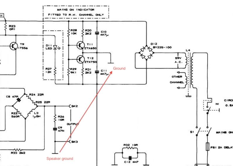
The 606 uses a single fuse on the A/C output of the transformer secondary for each channel, and a virtual 0V line is extrapolated after the PSU by mounting a 470nF cap from + and - rails to the centre. See here and here.
As an illiterate I need to ask a couple of questions:
1. I see how the 0V will now always be at the centre of the p.d. between the other two rails, even if one side develops a fault and I see how the fuse will blow if the total current draw increases because of that fault, but I don't see how this will provide a quick shutoff to the speakers if for example an output transistor fails, as the caps will need to discharge after the fuse blows. I'm guessing T15(11) and T16(12) are the answer to this, but the 606 operates on slightly higher (and slightly offset) voltage rails, so how can the design be changed to power the 405 safely while removing the DC clamp and PCB fuses?
Then there's the whole grounding topology:
The 405 has two grounding points, one at the signal input and the other at the other side of R2 for the dumpers. In the original case and with the original shared PSU both ends are connected to 0V through the chassis.
With independent, virtual grounds I'm more flexible, but also have far more potential for mistakes.
2.The 606 schematic gives a clue because it looks like the virtual 0V is only connected to Chassis/GND through R40/C14, but does that "lift and separate" (pardon the pun) my 0V rails as much as possible? Could I add a diode isolator like this:
An externally hosted image should be here but it was not working when we last tested it.
(read "Boat" and "Shore" as "0V" and "Chassis").
3. Regardless of 2: What is the best grounding topology for each channel:
a. Where should I connect:
- "Signal ground
- Speaker Ground
Chassis?/0V?
As an illiterate I have to say I don't understand the function of R2. If one end only were connected to 0V then I could see that it would "lift" the other so we don't pollute the input with dirty dumper stuff. We see where the dumper end only is grounded in some faulty 405's that R2 can fry quite quickly, so this clearly doesn't work, but won't there always be a direct path between "dumper 0" and "signal 0" as long as both are connected to chassis/common grounding point. Isn't the only function then for R2 then to break the groundloop across the board?
Any feedback greatly appreciated!
Last edited:
Hi,
As Quad 405(-II) mods have been discussed a thousand times in these threads, I'll try to stay off the general discussion of what can be done to improve Quad's original design. After previously modding 4 405-II boards to Bernd Ludwig's design, I now want to try again and am building a 3 channel amp. based on Keith Snook's DCD-Mod4, which I'm told should be stable if done right.
The amp will be used to power the front 3 speakers in my 5.1 multimedia setup and (with an alternative decoder/preamp) the stereo pair when listening to music.
I do have quite a few questions, as I'm electronically pretty much illiterate, so please bear with me if I ask stupid questions!
I will be using three independent toroidal transformers and three power supplies in one cabinet, so getting the ground layout right will be one of my main challenges. However, as independent power supplies and secondaries allow for binning the much maligned DC clamp and output fuses, I'd like to start with that.
The 606 uses a single fuse on the A/C output of the transformer secondary for each channel, and a virtual 0V line is extrapolated after the PSU by mounting a 470nF cap from + and - rails to the centre. See here and here.
As an illiterate I need to ask a couple of questions:
1. I see how the 0V will now always be at the centre of the p.d. between the other two rails, even if one side develops a fault and I see how the fuse will blow if the total current draw increases because of that fault, but I don't see how this will provide a quick shutoff to the speakers if for example an output transistor fails, as the caps will need to discharge after the fuse blows. I'm guessing T15(11) and T16(12) are the answer to this, but the 606 operates on slightly higher (and slightly offset) voltage rails, so how can the design be changed to power the 405 safely while removing the DC clamp and PCB fuses?
Then there's the whole grounding topology:
The 405 has two grounding points, one at the signal input and the other at the other side of R2 for the dumpers. In the original case and with the original shared PSU both ends are connected to 0V through the chassis.
With independent, virtual grounds I'm more flexible, but also have far more potential for mistakes.
2.The 606 schematic gives a clue because it looks like the virtual 0V is only connected to Chassis/GND through R40/C14, but does that "lift and separate" (pardon the pun) my 0V rails as much as possible? Could I add a diode isolator like this:An externally hosted image should be here but it was not working when we last tested it.(read "Boat" and "Shore" as "0V" and "Chassis").
3. Regardless of 2: What is the best grounding topology for each channel:
a. Where should I connect:
- "Signal ground
- Speaker Ground
Chassis?/0V?
As an illiterate I have to say I don't understand the function of R2. If one end only were connected to 0V then I could see that it would "lift" the other so we don't pollute the input with dirty dumper stuff. We see where the dumper end only is grounded in some faulty 405's that R2 can fry quite quickly, so this clearly doesn't work, but won't there always be a direct path between "dumper 0" and "signal 0" as long as both are connected to chassis/common grounding point. Isn't the only function then for R2 then to break the groundloop across the board?
Any feedback greatly appreciated!
Hi
You have asked a lot of questions, its better to ask one or two, and get interest in your project from forum members first. But i am sure someone will have the patience to follow every move of the soldering iron you are making.
The diode bridge arrangement will work but not as you have drawn it. A bridge rectifier for isolating grounds like this is quite a good circuit.
Its discussed described and shown here, please read :
http://www.diyaudio.com/forums/power-supplies/112359-connecting-audio-ground-safety-earth.html
Cheers / Chris
Hi
The diode bridge arrangement will work but not as you have drawn it. A bridge rectifier for isolating grounds like this is quite a good circuit.
Its discussed described and shown here, please read :
http://www.diyaudio.com/forums/power-supplies/112359-connecting-audio-ground-safety-earth.html
Cheers / Chris
Thanks Chris!
That's already a very good tip!
I think I'm going for a ground topology like in the 606 but with the High Current Safety Loop Breaker Circuit as in figure 4 from your link.
Now all I need to do is work out how the 606 gets rid of the DC offset clamp circuit and I'm home and dry 🙂
Cheers!
Hi Learnincurve
i have seen that part of the 606 before, it looks like greatly assisting the bridge rectifier. I think build that little circuit up and see what it does- you will need to use same transistors or voltage current rating equivalents and resistors, also match with similar voltages. If we think of other arrangements like 10nf caps across each part of a diode bridge which was quite common in amplifiers , it appears to be doing that, possibly a better and a more clever way.
Regarding offset voltages, Quads excellent schematics usually give little voltage readings at various test points, so you could see where, they solve offset issues, and if there are any offsets.
hope that helps
Cheers / Chris
Hi, i seem to recall that the DC clamp on the Quad's i've seen, relies on a Triac to fire across the Output to blow a fuse/s when presented with a voltage above a certain level. If you can locate it & remove it, that "should" do what you want.
Hi Zero. Thanks for reply.
Yes. I'm sure that won't be a problem. I just don't want to do it unless I'm sure I have an alternative in place. Originally I was intending to go with Velleman K4700 kits (modified for faster detection and switching speaker to GND instead of amp out to N/C), but if the 606 power arrangement does the trick then I'll go with that as it makes my ground topology simpler.
Yes. I'm sure that won't be a problem. I just don't want to do it unless I'm sure I have an alternative in place. Originally I was intending to go with Velleman K4700 kits (modified for faster detection and switching speaker to GND instead of amp out to N/C), but if the 606 power arrangement does the trick then I'll go with that as it makes my ground topology simpler.
- Status
- Not open for further replies.
- Home
- Amplifiers
- Solid State
- QUAD 405 (mod): DC clamp and ground schema