Dissi, I just went over my simulation to refresh my memory and it turns out you were absolutely correct. My apologies. 😱
My sim was correct but I failed to transcribe it correctly. I had the tweeter and mid polarity reversed but I read them as the other way around. So reversed polarity on the woofer will achieve the same thing. Good catch.
That's the correct schematic?
Attachments
Very interesting project, as I said in the beginning, with a lot to read making it a challenge project for a start up and plenty info. I hope the results are good and that you're having fun (with the music and diy). 🙂
Congratulations and post some results as soon as you get. Regards.
Congratulations and post some results as soon as you get. Regards.
That's the correct schematic?
What is it you want to achieve with those RLC filters just
before driver terminals ?
C6 = 220 uF; Doesn't make sense.
C2 = 20 uF ??? The same
C7= 2 x 39 + 2 x 10 ; why not just 1x 100 ?
Can you measure impedance ?
What is it you want to achieve with those RLC filters just
before driver terminals ?
C6 = 220 uF; Doesn't make sense.
C2 = 20 uF ??? The same
C7= 2 x 39 + 2 x 10 ; why not just 1x 100 ?
Can you measure impedance ?
Aks jReave I didn't designed the Xover.
Aks jReave I didn't designed the Xover.
L6= 7 mH ( dcr= 1,15 ohm)
You don't want to spoil bass performance by adding unnecessary
resistance. Use ferrite or similar cored coils with lesser dcr.
0,4 or so is fine.
The xo I've done for merlin is based on a simulation using Paasive Crossover Designer and every component has been chosen to help achieve a flat response with the best phase alignment I could achieve at the xo's. (1st graph below) The sims use Zaph's measurements of each of the drivers to start off with.
This is a circuit I stole from Troels (for example here in one of his latest projects - ATS-4) to compensate for the rising impedance of the woofer at resonance and the way it interacts with the woofer's LP xo to produce an unwanted peak in the bass. (2nd graph is without LCR)
I'm am unsure what you mean by this?
The 220uF is part of the parallel LCR in series with the mid to tame it's peaking at about 750Hz. (3rd graph is without that circuit)
Third order on the tweeter increases its roll-off, improves the phase alignment at the xo and gives a flatter response than without. (4th graph is without it)
In trying to design a xo for somebody else without hearing or measuring it and without knowing exactly how much baffle loss to compensate for, I have designed a bit of flexibility in to the xo. This is one instance of that. If baffle step compensation needs to be adjusted for, C7 can also be adjusted in small steps to keep the response smoother and in fact the 10uF caps can also be used in the mid HP xo to help too.
What is it you want to achieve with those RLC filters just
before driver terminals ?
This is a circuit I stole from Troels (for example here in one of his latest projects - ATS-4) to compensate for the rising impedance of the woofer at resonance and the way it interacts with the woofer's LP xo to produce an unwanted peak in the bass. (2nd graph is without LCR)
C6 = 220 uF; Doesn't make sense.
C2 = 20 uF ??? The same
I'm am unsure what you mean by this?
The 220uF is part of the parallel LCR in series with the mid to tame it's peaking at about 750Hz. (3rd graph is without that circuit)
Third order on the tweeter increases its roll-off, improves the phase alignment at the xo and gives a flatter response than without. (4th graph is without it)
C7= 2 x 39 + 2 x 10 ; why not just 1x 100 ?
In trying to design a xo for somebody else without hearing or measuring it and without knowing exactly how much baffle loss to compensate for, I have designed a bit of flexibility in to the xo. This is one instance of that. If baffle step compensation needs to be adjusted for, C7 can also be adjusted in small steps to keep the response smoother and in fact the 10uF caps can also be used in the mid HP xo to help too.
Attachments
I'm am unsure what you mean by this?
Nothing, I am just used to fix things in a different way.
I deal only with measurements and never use simulation.
Sim graphs look good though.
Thanks for the answers !
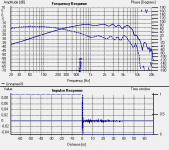
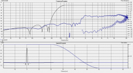
Some measurements done at 50cm from drivers mounted in the new front cabs with difraction.
WOOFER
TWEETER
WOOFER
An externally hosted image should be here but it was not working when we last tested it.
TWEETER
An externally hosted image should be here but it was not working when we last tested it.
Last edited:
Sorry merlin, I'm not experienced with measurement to offer you any advice. The graphs look about accurate for the Seas T25 and the Scan 8545 looks pretty similar to Troel's on-baffle measurements for his Amish revisted now although the real SPL levels with the same input might be more helpful. That looks like a nice flat tweeter response now that you have beveled the edges of the upper box.
What set-up and software are you using and are you able to measure the SB woofers too? Did you see this recent thread - http://www.diyaudio.com/forums/multi-way/250501-how-should-i-measure-speaker-crossover-creation.html - maybe it will help you.
What set-up and software are you using and are you able to measure the SB woofers too? Did you see this recent thread - http://www.diyaudio.com/forums/multi-way/250501-how-should-i-measure-speaker-crossover-creation.html - maybe it will help you.
Anyone can help me with the measurements?
You did the measurements of the raw drivers, right ?
Do the same with mic on the same spot for both drivers
with and without XO parts. I am assuming you have them,
Merlin the magician.
Sorry merlin, I'm not experienced with measurement to offer you any advice. The graphs look about accurate for the Seas T25 and the Scan 8545 looks pretty similar to Troel's on-baffle measurements for his Amish revisted now although the real SPL levels with the same input might be more helpful. That looks like a nice flat tweeter response now that you have beveled the edges of the upper box.
What set-up and software are you using and are you able to measure the SB woofers too? Did you see this recent thread - http://www.diyaudio.com/forums/multi-way/250501-how-should-i-measure-speaker-crossover-creation.html - maybe it will help you.
I used different lineamps with different gain, SB lineamp with more gain (valve mu-follower ECC81) & #26 preamp with less gain.
I'm using Holm as soft, the hard is: mic Behringer ECC8000, soundcard M-Audio mobile-pre USB.
Measurements both 50cm form driver on axis (woofer & tweeter).
I will look in your link, thank you.
You did the measurements of the raw drivers, right ?
Do the same with mic on the same spot for both drivers YES
with and without XO parts NO ONLY WITHOU XO. I am assuming you have them, i HAVE THE PASSIVE XO DESGINED BY JREAVE
Merlin the magician.
Merlin,
do the measurements with parts you have and post it here.
Leave the mic on the same spot. Place it wherever you want.
Between the drivers in front of them or wherever you like.
Just leave it be. Do not change the height of the mic at all.
Record separately bass and tweeter and their sum.
do the measurements with parts you have and post it here.
Leave the mic on the same spot. Place it wherever you want.
Between the drivers in front of them or wherever you like.
Just leave it be. Do not change the height of the mic at all.
Record separately bass and tweeter and their sum.
Below are the simulations I used for your ScanSpeak and Seas on a chamfered baffle - you can see that they are quite close to what you have measured but that there are some differences too. For the Scan, the peak at about 750Hz is gone which is probably accurate (that agrees with Troels' measurement I think) and that's a good thing. But I'm a little suspect on the response below 2000Hz on the tweeter and below about 200Hz on the mid. See if this paper helps you at all:
New Paper available on How to Get Accurate Measurements Indoors Down to 10 Hz
Once you feel like you have accurate measurements of all 3 drivers, I can take those graphs and use them to fine tune the xo. But 2 things you should know. First, all 3 drivers should be measured with the same input, usually 1 watt or 2.83v. Although you will probably want to fine tune the mid and tweeter levels by ear in the end, I need to work with the same input level for all 3 drivers.
And second, place your mic directly in front of each driver at the same far-field distance when you measure each one of them. Don't measure them all without moving the mic up or down for each one. The program that I use (PCD) uses the on-axis measurements to start off with and then accounts separately for the different placements of the drivers on the baffle afterwards.
Attachments
Merlin,
do the measurements with parts you have and post it here.
Leave the mic on the same spot. Place it wherever you want.
Between the drivers in front of them or wherever you like.
Just leave it be. Do not change the height of the mic at all.
Record separately bass and tweeter and their sum.
How many uF the cap for the tweeter to do the sum measurement? can be enough 24uF because I have one on hand?
Last edited:
Below are the simulations I used for your ScanSpeak and Seas on a chamfered baffle - you can see that they are quite close to what you have measured but that there are some differences too. For the Scan, the peak at about 750Hz is gone which is probably accurate (that agrees with Troels' measurement I think) and that's a good thing. But I'm a little suspect on the response below 2000Hz on the tweeter and below about 200Hz on the mid. See if this paper helps you at all:
New Paper available on How to Get Accurate Measurements Indoors Down to 10 Hz
Once you feel like you have accurate measurements of all 3 drivers, I can take those graphs and use them to fine tune the xo. But 2 things you should know. First, all 3 drivers should be measured with the same input, usually 1 watt or 2.83v. Although you will probably want to fine tune the mid and tweeter levels by ear in the end, I need to work with the same input level for all 3 drivers.
And second, place your mic directly in front of each driver at the same far-field distance when you measure each one of them. Don't measure them all without moving the mic up or down for each one. The program that I use (PCD) uses the on-axis measurements to start off with and then accounts separately for the different placements of the drivers on the baffle afterwards.
I measured with my tru rms meter and 2.83V is too loud...
- Status
- Not open for further replies.
- Home
- Loudspeakers
- Multi-Way
- Help for 3 or 4 way loudspeaker