It is "hum" from AC filament supply, 60Hz and its harmonics here in the U.S.Ihquam. I do wonder what this is about. Tubes dont make that kind of noice but they can of course pick it up from something. We have to figure out what differs the tube brands in this build. I take it the build had an input transformer. First question: what kind of noice was it, 100 Hz with overtones?
Cannot spot any input transformer... http://www.diyaudio.com/forums/pass-labs/136835-impasse-preamplifier-77.html#post3792273
Arne K
Arne K
Cannot spot any input transformer... http://www.diyaudio.com/forums/pass-labs/136835-impasse-preamplifier-77.html#post3792273
Arne K
That's Katies build. I was talking about luvdunhill's Impasse build that Ihquam measured. That has now been answered.
The noise in my Impasse is in the mid tens of uV. The noise in the F4 which the Impasse was designed to drive is around 50uV. The best of tube preamps are in the low 10's of uV.
I should have stated this a bit differently -- on the FFT the baseline is in the mid tens of uV -- but when I switched in the CCIR-2K filter with "Average" metering the integrated value was 400 to 500uV -- consistent with what others have observed. CCIR-2K is the standard that Dolby preferred, feeling that A-weighting didn't correspond well with human observations.
I've reviewed most of John Atkinsons's tube pre reviews, I like the Nagra!
I wouldn't have thought that layout would add considerably to the "hiss" element of noise, maybe hum but mine is hum free. The layout is almost identical to another published project on here.
I haven't had a chance yet to try some of the suggestions above or to get the scope in there.
The original tubes were cheapies from E-Bay, I've replaced the 6SN7 with an Electro-Harmonix and I'm waiting for an E-H ECC88.
Originally I did have problems with the CCSs but that was sorted with SY's help.
I must add that I am yet to add the two caps between the heater supplies and Gnd.
And of course, mine doesn't have the input transformers, it is driven by a B1.
Last edited:
During the initial discussions when building the Impasse, I was lead to believe the the input transformers would be unnecessary with short input leads and a high impedance source.
I'm very loathe to spend nearly £150 on two transformers if they are not going to make any difference.
I'm very loathe to spend nearly £150 on two transformers if they are not going to make any difference.
I have very successfully built an Impasse without input transformers. A high impedance source is not required, just close proximity to avoid ground loop issues. All of the hum from my Impasse is due to filament/cathode coupling, not ground loops.During the initial discussions when building the Impasse, I was lead to believe the the input transformers would be unnecessary with short input leads and a high impedance source.
I'm very loathe to spend nearly £150 on two transformers if they are not going to make any difference.
I have very successfully built an Impasse without input transformers. A high impedance source is not required, just close proximity to avoid ground loop issues. All of the hum from my Impasse is due to filament/cathode coupling, not ground loops.
I tested the Impasse pre without transformers -- this shouldn't be an issue from what I observed.
I keep goin' back to what I said about the CCS -- measure the voltage drop across the 12k5 resistors -- if it's over 100V by 20% or more there's trouble in River City.
That's a ridiculous price, it's a cheap transformer. Source something more local or from someone who knows how to get product into Europe at a reasonable cost (Antek, perhaps?).
I've read that we're advised to avoid toroid.
Is there any changes required when I use toroid?
Is there any benefit to using Cree Zero Recovery Schottky Diode?
Thanks!
Toroid will work fine, but pay particular attention to the grounding, since they can couple in line noise very efficiently.
Any fast recovery diode will perform well. The main advantage of Schottky is the lower voltage drop, but that's absolutely irrelevant at 300-400V.
Any fast recovery diode will perform well. The main advantage of Schottky is the lower voltage drop, but that's absolutely irrelevant at 300-400V.
SY and/or jackinnj:
Going back to post #642 http://www.diyaudio.com/forums/pass-labs/136835-impasse-preamplifier-65.html#post3668273, where I replaced the LEDs with a resistor (and trimpot) in order to adjust Vgk, it was suggested that I add a suitably large capacitor across the resistance. I have done simulations and actual measurements and have not detected any noticeable improvement by adding such a cap. Without the cap, the output impedance is approximately tripled from about 7.5K to about 21K (Zout=Rload || (Rplate+ (mu+1)*Rcathode)), but with grid capacitance of the 6922 being about 8pF plus wiring parasitics, the cutoff frequency is fc = 380kHz. The gain reduced by less than 1%. Am I missing something?
BTW: Since I am trying to increase Vgk to around 5.0V-5.5V, another option is to add the resistance in series with the 2 LEDs. This results about 1/3 the additional cathode resistance.
Your calculations are right, the limitation is the transformer, but you may see an increase in distortion.
If you use 3 red LEDs, the voltage will be about 5V, pretty close to your target. At the same time, the plate voltage will go up- make sure that you still have reasonable operating points on the cathodyne (you may have to adjust the step network) and that you're not threatening the compliance of the CCS.
If you use 3 red LEDs, the voltage will be about 5V, pretty close to your target. At the same time, the plate voltage will go up- make sure that you still have reasonable operating points on the cathodyne (you may have to adjust the step network) and that you're not threatening the compliance of the CCS.
The new ECC88 has arrived but I haven't had an opportunity to fit it yet. The CCSs are OK, I'll fit a tightly twisted B+ supply cable and fit the two heater caps at the same time. I'll report back when I'm done.
Just to re-iterate, this is a high frequency noise "hiss", not mains born "hum".
Just to re-iterate, this is a high frequency noise "hiss", not mains born "hum".
I'm getting round to thinking that this may be PSU orientated.
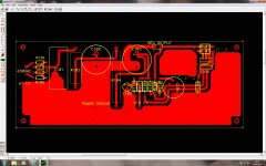
I did post the PCB at post #626 but I'll copy it here for any comments.
C101 now has an additional 100uF/450V across it as my mains transformer was a bit on the low side for the regulator without additional reservoir capacity.
R103 and R104 were also reduced to 100R in order to increase the voltage input to the regulator.
Attachments
Last edited:

- Home
- Amplifiers
- Pass Labs
- ImPasse Preamplifier