Put the 75us RC in as an output filter.
It rolls off to very high frequencies AND attenuates the added noise of all the previous stages. 75r +-0.5% and 10n +-0.5% gives very good accuracy, if the output impedance can be held very accurately to VHF.
The preceding stages only need the 318us and 3180us parts of the RIAA.
It rolls off to very high frequencies AND attenuates the added noise of all the previous stages. 75r +-0.5% and 10n +-0.5% gives very good accuracy, if the output impedance can be held very accurately to VHF.
The preceding stages only need the 318us and 3180us parts of the RIAA.
I have not checked your RIAA calculations. Find the famous Lipschitz paper and it will tell you all you need to know.
Lipschitz papers are not needed. I have enough math skills to calculate
those component values by myself (not to say that I'm proud of
myself...I've just been messing with this kind of math (and math
in generally) for ages (for decades, huh!)).
R1=4.33M
R2=369K
C1=736pF
C2=202pF
R1xC1=3186.88µs (deviation to 3180µs about 0.2%)
R2xC2=74.5380µs (deviation to 75µs about 0.6%)
R1xR2/(R1+R2)x(C1+C2)=318.942µs (deviation to 318µs about 0.3%).
...Regards MK
Summa summarum: Here is the “designers math” for my shunt feedback RIAA stage
having two resistors and two capacitors in the feedback chain (i.e. Z = R1││C1 + R2││C2):
If
A: dc gain of the stage (100 in my case)
f1,f2,f3: RIAA frequencies (f1=50.05Hz, f2=2121.5Hz, f3=500.5Hz)
R: input resistance (47k)
then:
R1 = Ax(1-f1/f3)/(1-f1/f2)xR = 0.92175xAxR (= 4.3322M)
R2 = (1-f3/f2)/(f3/f1-1)xR1 = 0.084898xR1 (= 367.80k)
C1 = 1/2/π/f1/R1 (= 734.02pF)
C2 = 1/2/π/f2/R2 (= 203.97pF).
Hi MK,
With all respect, your values are correct but impractical do to resistor noise. One can get better noise figures by dividing all Rs by 50 to 100, and multiplying all Cs by the same amount. In this case the circuit must be able to deliver sufficient current into the capacitors' reactance esp. at high frequencies, in order to avoid slew rate limitation.
With all respect, your values are correct but impractical do to resistor noise. One can get better noise figures by dividing all Rs by 50 to 100, and multiplying all Cs by the same amount. In this case the circuit must be able to deliver sufficient current into the capacitors' reactance esp. at high frequencies, in order to avoid slew rate limitation.
Hi MK,
With all respect, your values are correct but impractical do to resistor noise. One can get better noise figures by dividing all Rs by 50 to 100, and multiplying all Cs by the same amount. In this case the circuit must be able to deliver sufficient current into the capacitors' reactance esp. at high frequencies, in order to avoid slew rate limitation.
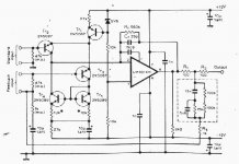
There is a buffer following RIAA stage giving extra gain of 20dB as shown in the attachment
of my first post. This buffer loads RIAA stage with resistor of 3.3k so there is no capasitive
load in the output of RIAA stage. Capacitors in the feedback chain are not loading the op amp
because it is not feeding them. Furthermore, capacitance values don’t affect the dc gain of this stage.
If I lower the resistance values the dc gain (A) will go down. I choose it to be 100 (40dB)
so that the total dc gain is 1000 (60dB) which means 40dB@1kHz.
Resistor noise comes from the input resistor (47K), not from the resistors in the feedback chain
because they are effectively parallel with input resistor (it’s resistance added with cartridge
coil resistance). This noise cannot be avoided if I prefer shunt feedback configuration as I do.
…Regards MK
The way I see it, and feel free to correct me if I'm wrong, is the feedback network in this configuration is essentially at ground on both sides due to the virtual ground at the inverting input and the output ideally being a voltage source, so it should make almost no contribution to overall noise. The network does, however, load the op amp output since it is essentially connected from output to ground, so it is necessary to be sure it does not present too low a load impedance at high frequencies. The OP's circuit probably does not load the op amp output excessively with the small capacitance values given.
Trying to use a shunt feedback circuit with the phono cartridge directly connected to its input will require the 47K resistor and its significant thermal noise contribution. The way around that is to use a buffer between the cartridge and the shunt feedback amplifier input so the amplifier's resistors can be made lower in value therefore contributing less to noise. Of course that requires an op amp stage connected in a series feedback configuration as a non-inverting unity gain amplifier (or some sort of discrete transistor circuitry). The op amp operating at unity gain should offer its best distortion and noise performance since it provides no gain and there are no resistors in the feedback network.
-Erich
The way I see it, and feel free to correct me if I'm wrong, is the feedback network in this configuration is essentially at ground on both sides due to the virtual ground at the inverting input and the output ideally being a voltage source, so it should make almost no contribution to overall noise.
Doesn't the Johnson noise of the feedback network have a corresponding current noise?
Doesn't the Johnson noise of the feedback network have a corresponding current noise?
I would say if there is a voltage across a resistor then there would have to be a current through it as well. I'm having to learn about noise on my own, so I will probably get it wrong at first, but I am doing my best to figure it out.
What I think I got wrong was the op amp input, while essentially at ground, is not the same as being directly connected to ground. If it were, there could be no output signal. It just looks like ground because feedback it doing its best to keep the inverting input the same as the non inverting input (in this case, connected to ground). So there still has to be a current flow at the inverting input, and the feedback resistor noise is going to contribute to overall noise. The outcome is still the same; keep resistor values as low as practical for lowest noise.
Not only that. Perhaps more importantly, it also handles RFI much better.
Is that because the inv input is at virtual ground?
jan
Hi,
FWIW the noise difference between shunt and series depends on the cartridge.
Typical MM's have high enough inductance used in shunt to transfer the
effective noise source impedance from the cartridges resistance to the
47K input resistor, i.e. shunt has lower noise at low frequencies.
Low inductance cartridges like HOMC's, and medium like some Grado's
are better with the shunt arrangement if noise is the major concern.
However as JLH noted, in real life with most MM's, series has
nowhere near the noise disadvantages claimed, often about
1K source impedance is assumed for the shunt calculations.
If this assumption is reasonable, shunt will clearly be quieter
than series, if it isn't, the differences are less clear cut.
I find the supposed "inaccuracy" of shunt compared to
series quite amusing. Easy to meaninglessly fix though.
rgds, sreten.
Read post 27 carefully.
The currents through the input resistor and feedback resistor will sum to zero at the inverting input. Assuming an ideal noise-free op amp, the output will do what it needs to do in order to keep that node at zero. Since the feedback resistor has a noise voltage (and therefore current), the op amp output is going to have an equal noise voltage attempting to keep the inverting input at zero, so the noise contribution at the output is equal to the Johnson noise of the feedback resistor. Of course the noise contribution of the input resistor will be its Johnson noise voltage multiplied by the amplifier gain. This still does not take into account the noise contribution of the op amp itself, which is going to depend on the value of the input resistor and the source impedance, and I would think it would be significant with a 47K resistor. LP surface noise is probably going to dominate, but I don't see the need to have more amplifier noise than necessary.
-Erich
The way I see it, and feel free to correct me if I'm wrong, is the feedback network in this configuration is essentially at ground on both sides due to the virtual ground at the inverting input and the output ideally being a voltage source, so it should make almost no contribution to overall noise. The network does, however, load the op amp output since it is essentially connected from output to ground, so it is necessary to be sure it does not present too low a load impedance at high frequencies. The OP's circuit probably does not load the op amp output excessively with the small capacitance values given.
Trying to use a shunt feedback circuit with the phono cartridge directly connected to its input will require the 47K resistor and its significant thermal noise contribution. The way around that is to use a buffer between the cartridge and the shunt feedback amplifier input so the amplifier's resistors can be made lower in value therefore contributing less to noise. Of course that requires an op amp stage connected in a series feedback configuration as a non-inverting unity gain amplifier (or some sort of discrete transistor circuitry). The op amp operating at unity gain should offer its best distortion and noise performance since it provides no gain and there are no resistors in the feedback network.
-Erich
Thank you, Eric, for your comment. I am so much in love with shunt feedback concept that
I cannot accept series feedback buffer preceding my RIAA stage, “sorry”! And besides,
adding more SS-staff (ss=solid state) to signal path is always bad for the sound.
So, why I still think that the feedback chain in this stage is not loading the op amp?
It’s because the current running in it is the same as the current running in the input
resistor. So it is produced by the cartridge coil, not by the op amp and, in fact, op amps
output voltage is produced by this current. This is a bit mystical, but it all stems from the
fact that if op amps output is not saturated, then, because of large voltage gain, its input
lines can be seen as being shorted or, in fact, having so called offset voltage (little mV-voltage)
between them - and from the assumption that there is no current running in these lines
(no voltage, no current!). If op amps input stage is made using FETs, this assumption is well
justified because of the very low bias currents. Well, maybe you knew all this.
And once again: I’ve been listening to that 47k input resistor noise daily and I can assure that it is
not disturbing at all. The only sound heard when the needle is running in empty grooves is
the noise produced by the record surface. It covers the amp noise totally. So, why not opt
for shunt feedback configuration if it sounds better. Anyway, in theory, it should…
So, why not opt for shunt feedback configuration if it sounds better. Anyway, in theory, it should…
Shunt feedback may well sound better. But IMO, a phono stage not made from opamps (like Salas's JFET one which has a thread) wtll sound better than any phono stage based on opamps. 😛
Regards,
Andy
Hi,
Simply put :
In theory series is noisier, in practice not really with most MM's.
In reality series is pinker than than the whiter shunt, but at the
top end usually there is not enough difference to really matter.
The accuracy error, not that it matters, is easy to fix.
However I think a nail has been firmly struck on the head
in that many shunt arrangements place an odious load
on the gain stage, far more than the next stage, and
there is lot to be said for series for simple gain stages.
YMMV but better noise with worse distortion doesn't
make a lot of sense to me if the noise is not really
a problem in practical realiity, not paper specs.
rgds, sreten.
Shunt feedback may well sound better. But IMO, a phono stage not made from opamps (like
Salas's JFET one which has a thread) wtll sound better than any phono stage based on opamps. 😛
Regards,
Andy
Hi,
Except loads of phono stages not built from op-amps sound
far worse than than a standard op-amp phono stage mostly.
Non op-amp phono stages need far better power supplies
to compete, and in reality the above really makes no sense.
Its dogma. Reality isn't.
rgds, sreten.
Last edited:
Except loads of phono stages not built from op-amps sound
far worse than than a standard op-amp phono stage mostly.
Entirely agree. An opamp circuit with top quality opamps and passives and a really good power supply can compete with practically anything out there. It may show deficiencies in some areas, but overall it is quite amazing what can be achieved relatively easily and cheaply.
As a reality check against designs like Paradise or FS i keep a simple series feedback design consisting of a AD8610 followed by a buffer driving the feedback. At MM gain no coupling cap at output is needed. For MC there is a separate add-on stage based on parallel K170. Both are supplied by separate shunt regs.
Hi.
Let the figures tell how noisy my RIAA amp is (with OPA2134).
(Channels loaded only by oscilloscope (Fluke 123), turntable not running.)
Right channel:
rms voltage: 0.4mV (i.e. the noise voltage)
dc voltage: -2.7mV
Left channel:
rms voltage: 0.4mV
dc voltage: +4.4mV.
Let the figures tell how noisy my RIAA amp is (with OPA2134).
(Channels loaded only by oscilloscope (Fluke 123), turntable not running.)
Right channel:
rms voltage: 0.4mV (i.e. the noise voltage)
dc voltage: -2.7mV
Left channel:
rms voltage: 0.4mV
dc voltage: +4.4mV.
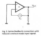
I do not think having ever read comments or experiences about Eric F. Taylor's phono preamp where the non-inteverting input of the circuit is connected to ground. It combines the advantages of low noise and low common mode distortion. The signal input is floating. It was described in a fairly known article : Eric F. Taylor 'Distorsion in low noise amplifiers' Electronics World August 1977, page 56.
Attachments
- Home
- Source & Line
- Analogue Source
- RIAA amp using shunt feedback