NON INVERTING Tilt Equalizer Filter have the same transfer function of the INVERTING Tilt Equalizer plus the level of the signal at the non inverting pin of the Amp-OP. See http://www.diyaudio.com/forums/analog-line-level/228632-tilt-equalizer-filter.html
Francesco Balena
Francesco Balena
having tested a version with a central frequency of 900Hz and a boost/cut of +/-6dB i think that it is too much and maybe a boost/cut of +-3dB (as in quad34) would be more appropriate.
The EDN link does'nt work anymore: try this:NON INVERTING Tilt Equalizer Filter have the same transfer function of the INVERTING Tilt Equalizer plus the level of the signal at the non inverting pin of the Amp-OP. See http://www.diyaudio.com/forums/analog-line-level/228632-tilt-equalizer-filter.html
Francesco Balena
Implement an audio-frequency tilt-equalizer filter | EDN
Ley me now if there are troubles. Francesco Balena
having tested a version with a central frequency of 900Hz and a boost/cut of +/-6dB i think that it is too much and maybe a boost/cut of +-3dB (as in quad34) would be more appropriate.
If you want the calculus of the components value let me now
the value of the potenziometer you will use ( ex. 50k Ohm)
Relating to boost/cut, remember that you can choise a different value for low freq and hi freq.
Ex.: boost/cut of (+-)6dB at low freq., and boost/cut of (+-) 3 dB at hi freq. Francesco Balena
yes if you have free time. the only thing im sure of ,is that +-6db at high frequencies is too much. so i would like +-3db at high frequencies, (a 50k pot will be used) .I am not sure about corner frequency and low frequency BOOST/CUT. maybe 900Hz AND +-3dB Boost/cut as well?
Hi maouna,
I will send you the components value for your request:
Fp= 900Hz, Pot=50k, Low-freq boost/cut=+-3dB, Hi-freq boost/cut=+-3dB. But first of all I need to post the reference jpg circuit fig. I don't remember where and how to store the fig, can you help me?
After that I will send you the data with your options and others as well (ex. Fp=440Hz, Low B/C=6dB, HI B/C 3 dB and more...)
Francesco
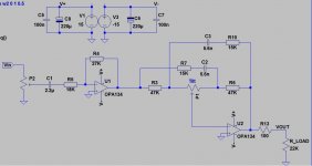
This is the reference schematic i am using now. the first opamp is configured for a small opamp. the second opamp as a tilt equalizer.the plot for the tilt equalizer opamp is attached.
you mean how to upload an image? you just click at ''go advanced'' button and then at ''manage attachements'' and select your file to upload.I don't remember where and how to store the fig, can you help me?
Attachments

Thank you maouna!
Here 's my reference schematic:
For your request P1=50k, Fp :900Hz, symmetric Boost/Cut +-3dB
the EXACT value are: C= 2.489 nF, Rf=121300 Ohm, R=50310 Ohm
Standard value: 2.4nF (5% toll), 121k, 49.9k ( 1% toll).


freq responce graphic and zoomed 900Hz pivot freq.
Soon I will post other responces. Francesco
Here 's my reference schematic:
For your request P1=50k, Fp :900Hz, symmetric Boost/Cut +-3dB
the EXACT value are: C= 2.489 nF, Rf=121300 Ohm, R=50310 Ohm
Standard value: 2.4nF (5% toll), 121k, 49.9k ( 1% toll).
freq responce graphic and zoomed 900Hz pivot freq.
Soon I will post other responces. Francesco
Thank you maouna!
Here 's my reference schematic: View attachment 395442
For your request P1=50k, Fp :900Hz, symmetric Boost/Cut +-3dB
the EXACT value are: C= 2.489 nF, Rf=121300 Ohm, R=50310 Ohm
Standard value: 2.4nF (5% toll), 121k, 49.9k ( 1% toll).
View attachment 395443 View attachment 395444
freq responce graphic and zoomed 900Hz pivot freq.
Soon I will post other responces. Francesco
thanks a lot..!
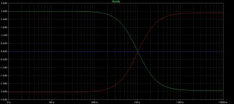
Hi,Values i could obtain were : 2.2nF, 120k, 51k which correspond at this graph below.Central frequency is about 1.024Khz.Later i am gone test it in real world....
I insert your values into my formulas and i get:
Centr.Freq. Fp= 1028.5Hz that's very near your simulation, and the same for the +/-3dB Boost/Att.
Testing an actual circuit shift a little bit these values because actual components have tollerance. If C=2.2nF have a 10% tollerance, the actual value you used could be between 1.98nF and 2.42nF. The same for resistors. Francesco
- Status
- Not open for further replies.
- Home
- Source & Line
- Analog Line Level
- OPA2134 Tilt Equalizer