For a chip amp that I built with a TDA7240, I want to get rid of the loud pop on power on and off. I tried the muting approach on the chip without success, so I need a circuit that delays the connection to the speakers at power on and switches off instantly the speakers at power off.
This circuit provides me the delay needed at power on (some seconds), but not the instantly switching off at power off: Power Amplifier Speaker Protection Circuit Schematic
I used a 47K trimmer and a 220uF cap with success.
Does anybody knows of a simple circuit that does what I need? If it will run with a 12V DC supply it would be great.
Thanks in advance, Ralf
Yes, I have seen that, for reference the link is: Loudspeaker Protection and Muting
However the circuit is designed for higher voltages than my 12V supply, and I don't know what components do I have to change (on figure 2 and 3) in order to make it work with 12V.
Can anybody give me some guidance?
Thanks, Ralf
However the circuit is designed for higher voltages than my 12V supply, and I don't know what components do I have to change (on figure 2 and 3) in order to make it work with 12V.
Can anybody give me some guidance?
Thanks, Ralf
For a chip amp that I built with a TDA7240, I want to get rid of the loud pop on power on and off. I tried the muting approach on the chip without success, so I need a circuit that delays the connection to the speakers at power on and switches off instantly the speakers at power off.
This circuit provides me the delay needed at power on (some seconds), but not the instantly switching off at power off: Power Amplifier Speaker Protection Circuit Schematic
I used a 47K trimmer and a 220uF cap with success.
Does anybody knows of a simple circuit that does what I need? If it will run with a 12V DC supply it would be great.
Thanks in advance, Ralf
Have a look at this.
SIMPLE UNIVERSAL SPEAKER DELAY
There are some video files of it in action in post #24 (playable direct in Windows media player)
The circuit would run off your mains transformer and is "isolated" in that it needs no connection to the audio grounds or any of the DC supplies in the amp.
Thanks Mooly, I think it is exactly what I need. I have some questions however:
1) Does the circuit work also with the BTA16-600B triac or need only the SW version?
2) Is the 9V AC from my transformer sufficient? Do I need to change some components? (zener, R3 ...)
3) What will be the series resistor in case of a 9V 180 Ohm relay?
4) Where do I connect the ground of the circuit?
Thanks in advance,
Ralf
giralfino... I'm just on my way out, I'll look at your questions later.
Can you tell me though, why only 9 volt ? What is your chip amp running on ? Ideally you should adapt the circuit to work of that voltage rather than a separate auxiliary supply.
Can you tell me though, why only 9 volt ? What is your chip amp running on ? Ideally you should adapt the circuit to work of that voltage rather than a separate auxiliary supply.
The chip is the TDA7240 which works with 12V DC. So I have a 230 to 9V AC transformer, followed by bridge rectifier and smoothing cap, providing 11 to 12 V DC to the chip. The amp works OK with plenty of power for my application (near field).
What I would do is to operate your circuit with the same 9V transformer, hence the questions. You're right, I don't want an auxiliary transformer for only the circuit!
Thanks, Ralf
What I would do is to operate your circuit with the same 9V transformer, hence the questions. You're right, I don't want an auxiliary transformer for only the circuit!
Thanks, Ralf
Well I think it could be made to work. The triac you would just have to try. The SW is the sensitive gate version and happened to be the one that I had. 10ma gate sensitivity vs 50 ma sounds a huge difference but here the gate is being pulled all the way down so I can't see a problem... but no guarantees. The trigger transistor (the 2N5551) really just shorts the supply out via the gate junction so it will pull whatever it needs until the triac fires.
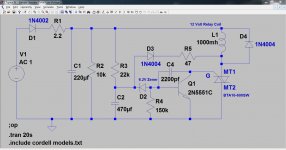
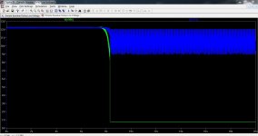
Here is a modified low voltage version. This is in simulation only but seems to work. Green is the voltage on the triac and blue the supply. The delay is set by R3 and C2. C1 will need tweaking to give an instant drop out and that depends on the relay current. So you need a few values on hand, say 100, 220 and 470 uf. The relay would be a 12 volt coil with either a lowish coil resistance to ensure the triac holding current is met or a higher resistance coil with a parallel resistor to give the minimum current needed. Trial and error. The zener is a lower voltage, say 5.6 or 6.2 volt.
Here is a modified low voltage version. This is in simulation only but seems to work. Green is the voltage on the triac and blue the supply. The delay is set by R3 and C2. C1 will need tweaking to give an instant drop out and that depends on the relay current. So you need a few values on hand, say 100, 220 and 470 uf. The relay would be a 12 volt coil with either a lowish coil resistance to ensure the triac holding current is met or a higher resistance coil with a parallel resistor to give the minimum current needed. Trial and error. The zener is a lower voltage, say 5.6 or 6.2 volt.
Attachments
Mooly,
thanks for your work, I'll give it a try and report back.
One question still remains: where do I connect the ground of the circuit? To the ground of the power supply after bridge rectifier and smoothing cap?
Thanks again,
Ralf
thanks for your work, I'll give it a try and report back.
One question still remains: where do I connect the ground of the circuit? To the ground of the power supply after bridge rectifier and smoothing cap?
Thanks again,
Ralf
For fast OFF, you can adopt the D.Self schematic that detects a missing pulse (or more) and directly trigger the relay to OFF.
Rather than waiting for the PSU to collapse.
Rather than waiting for the PSU to collapse.
Mooly,
thanks for your work, I'll give it a try and report back.
One question still remains: where do I connect the ground of the circuit? To the ground of the power supply after bridge rectifier and smoothing cap?
Thanks again,
Ralf
The ground can go directly back to the reservoir (smoothing) cap or the negative of the bridge as this is a single rail amp.
For fast OFF, you can adopt the D.Self schematic that detects a missing pulse (or more) and directly trigger the relay to OFF.
Rather than waiting for the PSU to collapse.
This is fast. Have you played the files showing it in operation ? Detecting absence of mains cycles is very precise, granted, but adds quite a bit to the complexity with the small signal circuitry needed.
Member
Joined 2009
Paid Member
I don't trust relays to break a dc current to an inductive load - at least not most of the relays I've seen for sale.
I do trust a solid state relay and implemented a simple circuit with delay on and fast off with solid state relay here: http://www.diyaudio.com/forums/solid-state/245619-tgm8-amplifier-based-rod-elliot-p3a.html
This circuit could be spun out on it's own small pcb if interested (PM me).
I do trust a solid state relay and implemented a simple circuit with delay on and fast off with solid state relay here: http://www.diyaudio.com/forums/solid-state/245619-tgm8-amplifier-based-rod-elliot-p3a.html
This circuit could be spun out on it's own small pcb if interested (PM me).
- Status
- Not open for further replies.
- Home
- Amplifiers
- Chip Amps
- Power on delay AND quick power off