Hello everyone,
I have been looking for some time for a high performance voltage regulator that I could use for all my low/medium power devices (DAC, preamplifier, headphone amp, etc.). There are some offerings out there, but few that were meeting my requirements, so I finally went to work.
What I wanted was:
-Fully discrete design (main reason was to make a nice complement to the Marsh headphone amplifier I have built, but also because I always favour discrete design when possible),
-Low noise,
-Low output impedance,
-High PSRR,
-Low distortion when applying signal to the rails,
-Impedance and phase response as flat as possible.
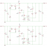
After looking at a lot of possible circuits, I finally settled on the POOGE 5.51 regulator, with an interesting improvement brought by ALW almost 12 years ago (see:http://www.diyaudio.com/forums/solid-state/1437-reducing-noise-voltage-regulators.html#post14171). I chose it for its impressive performance given the circuit relative simplicity. It can also be built for very little money: almost as cheap as regular LM317 regs for considerably better performance, really a no brainer 🙂
As a results, two boards were designed:
-One PSU board with rectifiers and main smoothing capacitors, to be put separately from the regulator and the circuit to be powered,
-One dual voltage regulator board, to be put as close to the circuit as possible.
The physical separation between the two is important for best performance, while allowing better flexibility in the process: you can put the rectifier board in a different enclosure if needed, or connect two regulators to one rectifier board, hence needing only one transformer.
Output voltage and current (depending on heatsinking, output device, and voltage reference used):
Output voltage: From +/- 3V to +/-40V
Max. output current: Up to 1A.
I am in the process of finalizing the PCBs, which I will soon have manufactured. I am thinking of producing more boards if some of you are interested.
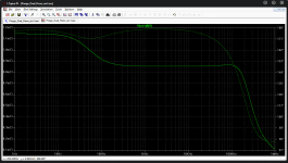
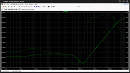
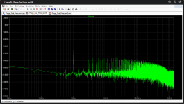
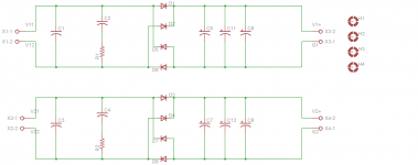
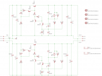
I will soon publish the pcb layout, in the meantime, here is the schematic, and some results of the simulated performance. From left to right:
1. Output Impedance and phase
2. PSRR
3. FFT at 1kHz
Feel free to ask any question. I am also opened to suggestions as the design is not completely final yet 🙂
Kind regards,
Sam
I have been looking for some time for a high performance voltage regulator that I could use for all my low/medium power devices (DAC, preamplifier, headphone amp, etc.). There are some offerings out there, but few that were meeting my requirements, so I finally went to work.
What I wanted was:
-Fully discrete design (main reason was to make a nice complement to the Marsh headphone amplifier I have built, but also because I always favour discrete design when possible),
-Low noise,
-Low output impedance,
-High PSRR,
-Low distortion when applying signal to the rails,
-Impedance and phase response as flat as possible.
After looking at a lot of possible circuits, I finally settled on the POOGE 5.51 regulator, with an interesting improvement brought by ALW almost 12 years ago (see:http://www.diyaudio.com/forums/solid-state/1437-reducing-noise-voltage-regulators.html#post14171). I chose it for its impressive performance given the circuit relative simplicity. It can also be built for very little money: almost as cheap as regular LM317 regs for considerably better performance, really a no brainer 🙂
As a results, two boards were designed:
-One PSU board with rectifiers and main smoothing capacitors, to be put separately from the regulator and the circuit to be powered,
-One dual voltage regulator board, to be put as close to the circuit as possible.
The physical separation between the two is important for best performance, while allowing better flexibility in the process: you can put the rectifier board in a different enclosure if needed, or connect two regulators to one rectifier board, hence needing only one transformer.
Output voltage and current (depending on heatsinking, output device, and voltage reference used):
Output voltage: From +/- 3V to +/-40V
Max. output current: Up to 1A.
I am in the process of finalizing the PCBs, which I will soon have manufactured. I am thinking of producing more boards if some of you are interested.
I will soon publish the pcb layout, in the meantime, here is the schematic, and some results of the simulated performance. From left to right:
1. Output Impedance and phase
2. PSRR
3. FFT at 1kHz
Feel free to ask any question. I am also opened to suggestions as the design is not completely final yet 🙂
Kind regards,
Sam
Attachments
Last edited:
Hi everyone,
Things have been pretty busy at work, but fortunately I was able to find some time to progress on the project. The design is almost completed now.
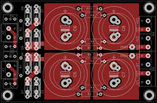
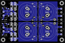
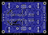
First, let's talk about the PSU board.
PSU board
I have designed the board with performance/flexibility/compactness in mind.
The first stage is a snubber network, to dampen the transformer ringing due to rectifiers switch-off. (see Morgan Jones' Rectifier snubbing in Linear Audio Vol.5, and Mark Johnson's quasimodo, here on DIYAudio).
The pcb can accomodate a lot of different rectifiers: from 1N4007 to higher current DO-41 packages, as well as TO-220 packages like MUR860, or the expensive Cree diodes.
A CRC filter is added after the rectifier stage to lower the AC ripple. Two resistors can be run in parallel. An inductor can also be added in place of one resistor if wanted.
The board is designed as a dual supply with completely independent (+,-) output, but can be easily wired for (+,-, Ground) output.
Things have been pretty busy at work, but fortunately I was able to find some time to progress on the project. The design is almost completed now.
First, let's talk about the PSU board.
PSU board
I have designed the board with performance/flexibility/compactness in mind.
The first stage is a snubber network, to dampen the transformer ringing due to rectifiers switch-off. (see Morgan Jones' Rectifier snubbing in Linear Audio Vol.5, and Mark Johnson's quasimodo, here on DIYAudio).
The pcb can accomodate a lot of different rectifiers: from 1N4007 to higher current DO-41 packages, as well as TO-220 packages like MUR860, or the expensive Cree diodes.
A CRC filter is added after the rectifier stage to lower the AC ripple. Two resistors can be run in parallel. An inductor can also be added in place of one resistor if wanted.
The board is designed as a dual supply with completely independent (+,-) output, but can be easily wired for (+,-, Ground) output.
Attachments
Last edited:
I prefer to use metallized film capacitors in snubber networks, because of their excellent dissipation factor (tan δ).
The ones I chose for my most recent PCB were in a "box" package: (link to EPCOS snubber cap)
The ones I chose for my most recent PCB were in a "box" package: (link to EPCOS snubber cap)
Sam,
The regulator circuit and its performance look pretty good.
One thing when I consider a regulator is how it interacts with the load. We must see the regulator and the load to be one circuit. Most audio line level circuits require local bypass and most opamp datasheets indicate 0.1uF ceramic capacitor bypass close to the opamp supply pins. Regulators have rising impedance at the output which means the output is inductive. This can form LC resonance with the load. Some regulators do not tolerate large capacitance or high Q ceramic / film capacitors at its output.
Regards,
Bill
I agree. I think it is better to place the large caps before the regulator and allow the output of the regulator to drive the load like the amplifier it is. Use small film caps where necessary such as Op-Amp decoupling, ect. Try placing a 1000uf cap across the output of an audio circuit and see what happens.
the snubber caps look like they are "box" type. Have a look at using X7R instead.
The snubbers caps are "box" types on the pcb only to allow multiple choices (film caps generally need more real estate), and fitting ceramic caps instead is of course possible (btw, that was my intention before I saw Mark's comment).
I prefer to use metallized film capacitors in snubber networks, because of their excellent dissipation factor (tan δ).
The ones I chose for my most recent PCB were in a "box" package: (link to EPCOS snubber cap)
Thanks for the input Mark.
If you optimize your snubber using a bellringer approach, in which you dial the snubber resistance while stimulating your actual transformer's secondary into oscillatory ringing, you can try all sorts of different capacitor packages, dielectrics, and capacitance values. The great joy is: the oscilloscope shows you exactly how the full snubber performs and you can judge for yourself whether it's satisfactory.
You don't need to rely on somebody else's opinion of what capacitors are best, or worst, or preferable, or awful. Buy your own snubber components according to your own judgment, install them into your bellringer jig, connect up your transformer and scope, then measure. Hard data is more valuable than opinion; measurements trump pronouncements.
You may discover that those multicolored "tropical fish" capacitors sitting in the bottom of your junkbox, do a wonderful job of snubbing your transformer. You may find that the cheapest capacitors your vendors sell, perform quite admirably in snubbing applications. With bellringer testing, snubber performance is 100% observable, to steal a phrase from CPU test engineers. Doesn't matter what Tom, Dick, or Harry say about how a certain component "should" perform; hook it up and see how it actually performs.
A search of this website will find threads that discuss bellringer test jigs, including a jig called Quasimodo which I originated.
"The wise learn from the experience of others, the unwise only from their own" (John Lubbock). That doesn't mean you don't question what you have learnt afterwards.
I am aware of the bellringer jigs, I am planning to do those tests, and more.
I am aware of the bellringer jigs, I am planning to do those tests, and more.
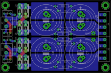
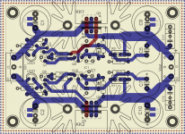
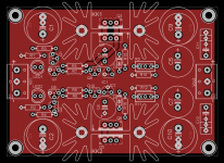
Suggested improvement : since it looks like a double sided board, use power and ground planes below the big caps. The capacitor charging pulses will emit less magnetic field. Think about the loop area. Also the thermals on the big cap pins don't look very useful...
Sam,
The regulator circuit and its performance look pretty good.
One thing when I consider a regulator is how it interacts with the load. We must see the regulator and the load to be one circuit. Most audio line level circuits require local bypass and most opamp datasheets indicate 0.1uF ceramic capacitor bypass close to the opamp supply pins. Regulators have rising impedance at the output which means the output is inductive. This can form LC resonance with the load. Some regulators do not tolerate large capacitance or high Q ceramic / film capacitors at its output.
Regards,
Bill
I agree. I think it is better to place the large caps before the regulator and allow the output of the regulator to drive the load like the amplifier it is. Use small film caps where necessary such as Op-Amp decoupling, ect. Try placing a 1000uf cap across the output of an audio circuit and see what happens.
The 1000uF mentioned is only written as an indication, and everyone can put the capacitance best suited for the load. I will edit schematic with lower value to be safer. Still, placing a reasonably large capacitance at the regulator output is important to compensate the impedance rise with frequency above ~20kHz. I recommend at least 330uF in total. Since the pooge regulator is reported to be very stable with various loads, that should not be a problem (to be confirmed with testing). It is better to put most of this capacitance as close as possible to the load, of course, if the amp board permits it.
Last edited:
Suggested improvement : since it looks like a double sided board, use power and ground planes below the big caps. The capacitor charging pulses will emit less magnetic field. Think about the loop area
Good idea.
Please explain? Soldering the caps would be more difficult without thermal relief.Also the thermals on the big cap pins don't look very useful...
Attachments
Please explain? Soldering the caps would be more difficult without thermal relief.

(I got mine for 5€ at flea market). If you don't have one, then yes, use thermals.
where is the output voltage referenced to ?
(hint : probably the voltage reference pin which is connected to GND)
you should connect this to GND output pin (on output connector) to increase precision...
(hint : probably the voltage reference pin which is connected to GND)
you should connect this to GND output pin (on output connector) to increase precision...
- Status
- Not open for further replies.
- Home
- Amplifiers
- Power Supplies
- High performance PSU and voltage regulator