Looks great! How much would your friend charge for the PCB?..... PCB dual mono made by a friend of mine 🙂
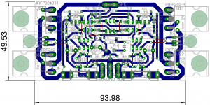
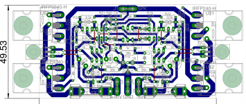
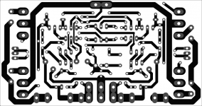
I had some time on sunday and I made v1 pcb, zobel and output coil is fitted in psu board. Why pcb is in that shape ? --> cause It must fitt my ebay enclosure, max hight 60mm and very little room inside (14cm wide only). Later on Ill post some updates.
If someone can spot some faults -- thanks for raport.
Thanks Greg !!!
If someone can spot some faults -- thanks for raport.
Thanks Greg !!!
Attachments
Member
Joined 2009
Paid Member
If someone can spot some faults
Nice layout & great to see more folk taking up the challenge of making their own pcb design. Some quick comments in case it is helpful at all:
Input cap: if you can't fit a large film cap then it's better, in my view, to fit an audio grade bipolar electrolytic. I've had good results with this and so too has Ranchu32.
Power connectors are pretty close together with the GND. Not sure what size fuse you have but I used 2AG size, only 15mm long and readily available from Digikey.
MOSFETs like to self-oscillate, a provision for a 47R in series with 100p cap between gate and drain can be a lifesaver if needed.
R31 is a bit close between the MOSFET pins, why not move it 'north' to the other side of the gate pin (like you did for R11) ? same with R30.
R29 is weird at an angle, why not turn it parallel with C11, bring a short trace out from the gate pin of U$4 so R29 can be oriented north-south ?
R22 & R32 can be eliminated and use 10k 1W for R23 ?
I found it handy to have the input be a connector, if you make the pins spacing 0.1" you can choose to use a small header & connector, or pins, when you build it.
My boards (TGM7) are only 50mm and would fit on your heatsink - but it's much more fun to design your own pcb and mine is SMT which isn't everybodys cup of tea.
Last edited:
Thanks Bigun
I will putt some more effort to v2 version. The fuses are 20mm long and 5mm diameter. The input caps I am using wimas mks2 (red ones) the one on the board is 4.7uF (5mmx5mm footprit). What kind of bipolars would you recommend for input cap ? thx
I will putt some more effort to v2 version. The fuses are 20mm long and 5mm diameter. The input caps I am using wimas mks2 (red ones) the one on the board is 4.7uF (5mmx5mm footprit). What kind of bipolars would you recommend for input cap ? thx
Last edited:
Member
Joined 2009
Paid Member
Well I take back what I said as 4.7uf is already good so maybe it's no issue.
I used a wire link on my build but I have foot print for two sizes of bipolar, 10mm dia. with 5mm grid (Digikey 493-10847-1-ND) and the other for 5mm dia. 2mm grid (Digikey 493-10824-1-ND). On my TGM8 I'm using the larger one. These are audio grade Nichicon MUSE bipolar caps.
I used a wire link on my build but I have foot print for two sizes of bipolar, 10mm dia. with 5mm grid (Digikey 493-10847-1-ND) and the other for 5mm dia. 2mm grid (Digikey 493-10824-1-ND). On my TGM8 I'm using the larger one. These are audio grade Nichicon MUSE bipolar caps.
OT:
I'm looking for a good DIY amp to replace my LM3886 gainclone. Can this one be the answer ?
Or is there any easier ones as I'm not that great in electronics stuff other than soldering.
I'm looking for a good DIY amp to replace my LM3886 gainclone. Can this one be the answer ?
Or is there any easier ones as I'm not that great in electronics stuff other than soldering.
OT:
I'm looking for a good DIY amp to replace my LM3886 gainclone. Can this one be the answer ?
Or is there any easier ones as I'm not that great in electronics stuff other than soldering.
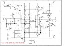
Definitely yes! But this board isn't the most suitable for beginners. It is sensitive to layout, wireing, grounding, parts, need matched output fets, and input bjt's, so must carefully to assemble, but the end you'll get a world class amplifier. If you order the kit directly from Greg Ball, you'll get a very good step by step assembly guide, if you choose the JIM'S PCB from ebay, ask some help to build the amp. Hard to beat SKA 150 in terms of sound quality.
If you are looking for a beginner discrete amp and intend to source parts yourself, I would not recommend this amp because it's a bit sensitive to parts matching.
Ok, thanks for the advice 🙂
The problem with ebay.com ordering is that my bank have an additional security layer which is not recognized with many international shopping sites. paypal is not supported.
So, ebay.com buying won't work.
May be you guys can recommend a good quality, more of a beginner level one on this thread 😉
http://www.diyaudio.com/forums/soli...ed-amp-vs-chip-amps-easier-achieve-n00bs.html
Member
Joined 2009
Paid Member
If you are looking for a beginner discrete amp and intend to source parts yourself, I would not recommend this amp because it's a bit sensitive to parts matching.
I don't think the LPT devices need to be matched because they are biassed to an unbalalanced operating point. Contrary to what Greg says about matching the high - Hfe of the input devices and I don't see any real obstacle to using B-grade parts; remember that he has a stock of C-grade parts that are no longer available so he may just want to protect the perceived value of his kits. The output FETs should be matched for Vgth but this isn't too much trouble and if they have separate source resistors this becomes less critical than the original version.
The more difficult issue with this design is the pcb - it's quite critical to get it right or you'll be fighting parasitic oscillations.
I have to say, after I found "My" mistakes, the amp plays very nice. As a matter of fact I have been listening to it all morning. The Jim's Audio boards don't use the BC*** parts for the LTP, they use 2SC and 2SA parts. I matched them because he said to but I don't know what would have happened if I hadn't. I thought it was important to match the outputs because they share only one source resistor, not one per. Am I wrong about that?
Thanks, Terry
Thanks, Terry
Attachments
Last edited:
My concern was with regard to the output devices. You need to buy a big batch and select parts, which then gets pricey.
It's good that you point out the PCB issue too, as it seems the guy may have to etch his own PCBs.
It's good that you point out the PCB issue too, as it seems the guy may have to etch his own PCBs.
Still4,
does your version have source resistors?
The standard 150 does not have any. It relies on good matching of the output devices to help equalise operating temperatures.
does your version have source resistors?
The standard 150 does not have any. It relies on good matching of the output devices to help equalise operating temperatures.
Member
Joined 2009
Paid Member
Greg does use a 0r15 source resistor, common to both NMOS and another common to to both PMOS parts, i.e. there isn't separate source resistors for each device. He recommends close matching. But as these devices have relatively high Rds-on the matching is less critical than you might think. I bought a batch of 25 FETs for my TGM7 build and when I tested them I found there was very little variation between them so that there was no need to buy very many of them at all.
- Home
- Amplifiers
- Solid State
- SKA GB150D now public domain...