After the success with my Raspberry Pi DAC it is time to go to the next level: a DSP that can be programmed directly from the Raspberry Pi.
First prototype is working, however I still have some issues with the analog input.

The DSP can be used as a sound card (stereo in/out) for the Raspberry Pi, but also as a standalone DSP. Programming is done directly from the Raspberry Pi. Unfortunately there is no free compiler for this DAC available. Therefore you have to use SigmaStudio. From there, the compiled program will be exported, transfered to the Raspberry and then written to the DSP. This is only needed when using a completely different program. Parameters for the running program can be updated on the fly. E.g. you can change filter frequencies of a crossover from command line.
The whole software is still in a very early stage, but the basic functionality is already working.
The DAC can be powered directly from the Raspberry Pi 5V supply, it consumes only 100mA.
First prototype is working, however I still have some issues with the analog input.

The DSP can be used as a sound card (stereo in/out) for the Raspberry Pi, but also as a standalone DSP. Programming is done directly from the Raspberry Pi. Unfortunately there is no free compiler for this DAC available. Therefore you have to use SigmaStudio. From there, the compiled program will be exported, transfered to the Raspberry and then written to the DSP. This is only needed when using a completely different program. Parameters for the running program can be updated on the fly. E.g. you can change filter frequencies of a crossover from command line.
The whole software is still in a very early stage, but the basic functionality is already working.
The DAC can be powered directly from the Raspberry Pi 5V supply, it consumes only 100mA.
This DSP uses the onchip ADCs/DACs of the ADAU1701. These are not the best DACs/ADCs on the market, but they perform reasonable well.
Sampling rate depends on the configuration. The DSP can work up to 192kHz, however in that case, there is less processing possible per sample. Therefore for complpex programs the sample rate might by limited to 48kHz.
Sampling rate depends on the configuration. The DSP can work up to 192kHz, however in that case, there is less processing possible per sample. Therefore for complpex programs the sample rate might by limited to 48kHz.
I still had some problems with the analog input which works now (just forget to solder a resistor on the other side). That means I can focus on the software development.
Is anybody interested to join the team? The software will be open source.
Is anybody interested to join the team? The software will be open source.
Looks good. Today I could finish the basic filter software.
I filters will can be configured by an XML file. Based on this file, the parameters for the filters will be calculated. Only BiQuads are implemented now, I will more on other filters in a later stage.
Here is an example (not the full file), which creates a Butterworth high- and lowpass:
<biquad name="bq11" input="input1" type="highpass1" frequency="200" q="0.7" />
<biquad name="bq12" input="bq11" type="highpass1" frequency="200" q="0.7" />
<biquad name="bq13" input="bq12" type="lowpass1" frequency="2000" q="0.7" />
<biquad name="bq14" input="bq13" type="lowpass1" frequency="2000" q="0.7" />

I will work on the web interface in the next days. The web interface will can run on the Raspberry Pi allow direct filter changes over the web interface.
I filters will can be configured by an XML file. Based on this file, the parameters for the filters will be calculated. Only BiQuads are implemented now, I will more on other filters in a later stage.
Here is an example (not the full file), which creates a Butterworth high- and lowpass:
<biquad name="bq11" input="input1" type="highpass1" frequency="200" q="0.7" />
<biquad name="bq12" input="bq11" type="highpass1" frequency="200" q="0.7" />
<biquad name="bq13" input="bq12" type="lowpass1" frequency="2000" q="0.7" />
<biquad name="bq14" input="bq13" type="lowpass1" frequency="2000" q="0.7" />

I will work on the web interface in the next days. The web interface will can run on the Raspberry Pi allow direct filter changes over the web interface.
Member
Joined 2009
Paid Member
Congratulations for your hard work! Your project looks very promising.
A quick note, although I'm not sure I understand the example below.
If you cascade 2 butterworth second-order sections, then you get a 4th order Linkwitz-Riley with cut-off point at -6 dB (as opposed to a 4th order butterworth with cut-off at -3 dB).
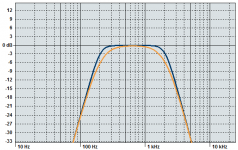
The difference between these filters is illustrated below, with same cut-off frequencies as yours (200 Hz and 2000 Hz). Butterworth is orange, LR is blue.

For some reason, your frequency response plot doesn't look like any of the 4th order Butterworth or LR, which is what you would normally achieve with 2 cascaded 2nd order sections.
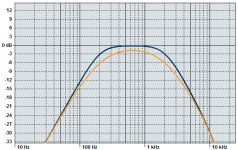
Below is the illustration of a Butterworth and a LR 2nd order (same cut-off frequencies). Your plot looks very much like the orange curve (which is again LR but 2nd order i.e. 12 dB/oct).

Normally you would need only one pair of biquads to implement these filters (one biquad for the low-pass and one biquad for the high-pass). But your example shows 4 biquads.
I can see 2 explanations:
- Your plot is not related to the XML example
- Or your biquads implement only 1st order sections, which is a waste of resources.
Wish you the best with your project!
Nick
A quick note, although I'm not sure I understand the example below.
Here is an example (not the full file), which creates a Butterworth high- and lowpass:
<biquad name="bq11" input="input1" type="highpass1" frequency="200" q="0.7" />
<biquad name="bq12" input="bq11" type="highpass1" frequency="200" q="0.7" />
<biquad name="bq13" input="bq12" type="lowpass1" frequency="2000" q="0.7" />
<biquad name="bq14" input="bq13" type="lowpass1" frequency="2000" q="0.7" />
If you cascade 2 butterworth second-order sections, then you get a 4th order Linkwitz-Riley with cut-off point at -6 dB (as opposed to a 4th order butterworth with cut-off at -3 dB).
The difference between these filters is illustrated below, with same cut-off frequencies as yours (200 Hz and 2000 Hz). Butterworth is orange, LR is blue.

For some reason, your frequency response plot doesn't look like any of the 4th order Butterworth or LR, which is what you would normally achieve with 2 cascaded 2nd order sections.
Below is the illustration of a Butterworth and a LR 2nd order (same cut-off frequencies). Your plot looks very much like the orange curve (which is again LR but 2nd order i.e. 12 dB/oct).

Normally you would need only one pair of biquads to implement these filters (one biquad for the low-pass and one biquad for the high-pass). But your example shows 4 biquads.
I can see 2 explanations:
- Your plot is not related to the XML example
- Or your biquads implement only 1st order sections, which is a waste of resources.
Wish you the best with your project!
Nick
Hi,
you're right. I mixed up Butterworth und Linkwitz-Riley. The Filter is a 2nd order Linkwitz-Riley, consisting of 2 first-order Butterworth filters (that's why it is named "lowpass1").
And you're also right, that a biquad filter for a first order filter is a waste of ressources. However, at the moment I have more than enough resources available. The SigmaDSP is really nice for this kind of applications, because it handles a BiQuad in 6 clock cycles. A first order filter would save 2 clock cycles. But using BiQuads even for first order filtering (with B2=A2=0) makes the implementation easier at the moment.
Daniel
Thanks, really interesting, and the Multipurpose GPIO could be used with external DACsin in the same pcb? Or the internal DACs of the ADAU1701 are good enough? Thanks
Looks good. This is like the miniDSP (from miniDSP.com not from TI) for Rasperry Pi - the DSP is the same one. Let's hope miniDSP.com won't steal your idea (or maybe you could sell your design to them). Look for extensions for next rev. if there will be one, folks need more outputs (at least 6x or even 8x for active speakers).
I had some issues with the available space on the board. Therefore not all IOs are available from the outside. But I might change this in a next release.
Not yet. As I'm busy with the DAC and the Digital output of the Raspberry Pi, this project is on hold at the moment. I'm also thinking about replacing the ADAU1701. Compared to my HiFiBerry DAC, the DACs on the ADAU1701 are not so good.
I'm also thinking about replacing the ADAU1701. Compared to my HiFiBerry DAC, the DACs on the ADAU1701 are not so good.
A OK, I think that would be the case, what DSP chip do you have in mind for replace the ADAU1701?
PCM5142 with two Raspberry Pi P5 headers for HIFIBerry for extra output channels? Or just two PCM5142's (4 channels)+ single P5 header (GPIO output from the other 42).
- Status
- Not open for further replies.
- Home
- Source & Line
- Digital Line Level
- DSP for the Raspberry Pi