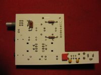
Picked up one of these portable amps to play with. My first impression was a bit of a shock at how hot it ran, i almost couldn't pick it up after a bit of use. I had a poke around the pcb and discovered the heater supply resistor was a .1ohm. Yup .1ohm so the element was getting 12v across it and ran hotter than the surface of the sun. If anybody buys one of these double check the resistor they have installed as its way too small..
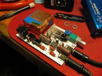
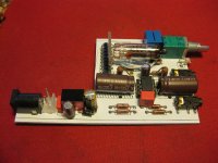
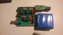
I tried a 7806 linear regulator to output 6.35v which worked ok except the regulator itself ran at ~70-80c with a small heatsink clipped on. I have since replaced it with a Traco unit, much better battery life and less heat, definitely the way to go. If you study the PCB there are two positions for transistor packages that are unused, i assume they had planned some sort of power manangement circuitry. By chance they are perfect fit for the Traco unit pin outs when mounted sideways, as per attached pic. Coupling caps are laid out as per datasheet.
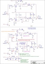
I've also attached a schematic i found on another forum, full credit to whoever actually created it as i have no idea. So far i have done the following,
-Replaced Ratheon 6111 tube with a NOS G.E. 6021A
-Replaced both 10k resistors with 20k adj pots and set to 6v DC. (9.3v with 6021A tube)
-Replaced all resistors with known quality metal film.
-Replaced all capacitors with Elna Silmic II.
-Added 10uf lytic / 100nf to Opamp power pins.
-Replaced blue led with red. ....i hate blue leds with a passion.
-Replaced NE5532 with a genuine LM4562.
-Replaced volume pot with a genuine Alps, cures crackly volume control.
-Installed Traco based heater supply.
The original tube (Ratheon 6111) got roasted alive with 12v across its heater so i replaced it with a NOS G.E. 6021A. Vs the 6111 that was installed it sounds much better, lower distortion, greater clarity, and more gain. I also have a 6BF7W and Russian 6N16b tube to try at some stage.
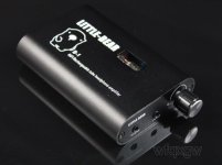
Basic amp can be bought from this seller, portable valve from woshixionghui2010 | eBay auctions typically end for £10-15. Traco regulator is ~£5, and a few quid for a few decent caps/resistors and you will have a very nice sounding little amp, highly recommended.
I tried a 7806 linear regulator to output 6.35v which worked ok except the regulator itself ran at ~70-80c with a small heatsink clipped on. I have since replaced it with a Traco unit, much better battery life and less heat, definitely the way to go. If you study the PCB there are two positions for transistor packages that are unused, i assume they had planned some sort of power manangement circuitry. By chance they are perfect fit for the Traco unit pin outs when mounted sideways, as per attached pic. Coupling caps are laid out as per datasheet.
I've also attached a schematic i found on another forum, full credit to whoever actually created it as i have no idea. So far i have done the following,
-Replaced Ratheon 6111 tube with a NOS G.E. 6021A
-Replaced both 10k resistors with 20k adj pots and set to 6v DC. (9.3v with 6021A tube)
-Replaced all resistors with known quality metal film.
-Replaced all capacitors with Elna Silmic II.
-Added 10uf lytic / 100nf to Opamp power pins.
-Replaced blue led with red. ....i hate blue leds with a passion.
-Replaced NE5532 with a genuine LM4562.
-Replaced volume pot with a genuine Alps, cures crackly volume control.
-Installed Traco based heater supply.
The original tube (Ratheon 6111) got roasted alive with 12v across its heater so i replaced it with a NOS G.E. 6021A. Vs the 6111 that was installed it sounds much better, lower distortion, greater clarity, and more gain. I also have a 6BF7W and Russian 6N16b tube to try at some stage.
Basic amp can be bought from this seller, portable valve from woshixionghui2010 | eBay auctions typically end for £10-15. Traco regulator is ~£5, and a few quid for a few decent caps/resistors and you will have a very nice sounding little amp, highly recommended.
Attachments

Last edited:
Split supply: Not much of a point here.
Opamp voltage follower with direct feedback usually works fine, only a few VFB types are fussy (e.g. AD797). Can't do that with a CFB opamp, obviously.
Blue LEDs: Me too.
Adding the 1k8 seems like a good idea, it makes the pot a fair bit more logarithmic.
The note on the schematic re: heater voltage actually isn't correct, underheating isn't exactly healthy either AFAIK.
Not sure why the output needs a pulldown as low as 2k2, is the 1000µ that leaky? Anyway, 2k2 >> typical loads, so who cares.
As in many of those cheap tube designs, plate current and voltage are quite low, which is not doing noise and distortion a favor. And they could've left out the 10 ohm cathode resistor entirely, it drops Vgc to a whopping -6 mV.
I like the idea with the transistor CCS instead of the plate resistor and variable cathode resistor (AC bypassed if needed) for DC adjustment.
If there's an opamp in there to begin with, I'd want to look into adding a negative feedback loop wrapping the OP and tube. That would require a non-unity gain on the OP though, and as such some sort of virtual ground.
Split supply: Not much of a point here.
Opamp voltage follower with direct feedback usually works fine, only a few VFB types are fussy (e.g. AD797). Can't do that with a CFB opamp, obviously.
Blue LEDs: Me too.
Adding the 1k8 seems like a good idea, it makes the pot a fair bit more logarithmic.
The note on the schematic re: heater voltage actually isn't correct, underheating isn't exactly healthy either AFAIK.
Not sure why the output needs a pulldown as low as 2k2, is the 1000µ that leaky? Anyway, 2k2 >> typical loads, so who cares.
As in many of those cheap tube designs, plate current and voltage are quite low, which is not doing noise and distortion a favor. And they could've left out the 10 ohm cathode resistor entirely, it drops Vgc to a whopping -6 mV.
I like the idea with the transistor CCS instead of the plate resistor and variable cathode resistor (AC bypassed if needed) for DC adjustment.
If there's an opamp in there to begin with, I'd want to look into adding a negative feedback loop wrapping the OP and tube. That would require a non-unity gain on the OP though, and as such some sort of virtual ground.
I've heard that before about running low heater power, just measured mine again and its got 6.37v at the tube.
I thought the 1000uf cap unusually large but have yet to replace it and measure the output for DC. I have a bunch of WIMA caps ~1uf i might try in its place.
I picked up a NOS G.E. 6021A tube to try so at the moment the 6v DC out of the opamp is at 9.3v, thats the lowest i can set with the 20k trimmers so i need to work out how to calculate the bias and cathode resistor values and sort them out. Can anybody help a tube newb with that?
Vs the 6111 that was installed its much better, lower distortion, greater clarity, and more gain. I think the original 6111 was partly fried with the 12v accross the heater as there are dark stains on the glass around the places the heater was exposed.
Hiya, I registered for an account just to make this post:
I'm very interested in performing the mods you've so awesomely documented here.
If you'd be so kinda as to go into some more detail about the caps on the opamp and how you've got the regulator hooked up (and which model) I'd really appreciate.
I consider myself pretty proficient at electronics, but can't totally infer the right way to do these mods. Thanks in advance!
Since you're using 12v supply I might as well suggest to use 12AE7, 12v dual triode for the tube.
Or jack up the supply voltage using voltage multiplier of the tube and use a coupling cap at the buffers input.This will make tubes work in their linear region and lower distortion.
Or jack up the supply voltage using voltage multiplier of the tube and use a coupling cap at the buffers input.This will make tubes work in their linear region and lower distortion.
Since you're using 12v supply I might as well suggest to use 12AE7, 12v dual triode for the tube.
Yeah, using a dual triode with different amplification factors between halves is probably not the best suggestion.
To get acceptable performance from something like this, you either need a space charge tube (resistant to non-linear grid current at low plate voltage), or a separate high voltage plate supply and your current tube (raising plate voltage will raise effective input impedance and reduce distortion, but at the expense of bulk).
You could probably also abandon the tube in favor of a pair of fets.
Hello, this is my first post here, and hopefully not the last 😉 I have been watching this thread for a long time, and I finally bought one of these babies, and it arrived today.
Having been warned about the heater voltage problem, I immediately opened it up to find out a green PCB from May 2014, so it has been redone. Unfortunately, the voltage problem persists, I measured about 9-10V across the heater, and immediately removed the 0.1 Ohm (Yes, 10^(-1)) resistor, thinking about replacing it with a 20 Ohm 5W.
However, I had a tiny 12V to 5V DC-DC converter from a car phone charger, and after connecting it to the heater instead of a resistor, it measured 6 to 6.5V, stabilizing around 6.3V, which is exactly the requirement for the heater!
Having that, I installed it inside and assembled the whole thing, and now I'm going for the stress test until it runs out of battery, and also checking for the temperature.
I also replaced the blue led for a red led from the same phone charger (my lucky day 😉 )
Nice work, i would love to see some pics of the latest board, specifically what was modified.
Here is a few close ups of the board version i have, its on my todo list to try a few of the suggestions from above, i.e. voltage doubler into a CCS circuit to drive the tube.
Here is a few close ups of the board version i have, its on my todo list to try a few of the suggestions from above, i.e. voltage doubler into a CCS circuit to drive the tube.
Attachments
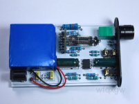
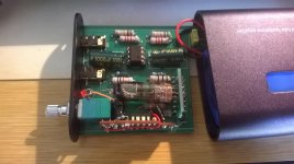
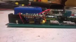
I attached a picture I took last night.
I basically removed the 0.1 Ohm resistor, and connected the Vcc of the extra board to the terminal connected to the positive voltage, and the terminal connecting to the heater to the 5V of the board. Since this was over dimensioned, it measured about 7V without any load, and with the heater, about the 6.3V necessary to run it.
I am not completely happy about the way everything is fitted inside, the wiring and the position of the extra board, since it's too close to the tube. I can't fit them near the battery as you have, for example. I am definitely not happy with the wiring, the closest ground was the LED's. If I had it connected directly to the battery ground terminal it'd be always on, since the power switch cuts off the ground.
Last night I managed about 3.5 hours, which isn't bad, but I heard about these things lasting more than 4 hours, so I'll look into it. The casing was mildly warm, yes, but not burning hot. Definitely comfortable to hold during the cold days!
Another concern that I have with the internal temperature is the battery life, which shortens with higher temperatures. I will have to find a way to insulate the battery from the direct heat of the tube, though there is no way to protect it from the casing, because it's a very tight fit and I doubt anything would fit over or under the battery.
Attachments
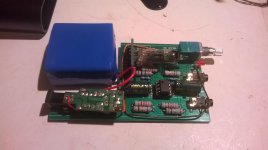
Hello, after breaking in the amp for the last weeks, I finally took the time to change the position of the step-down circuit board, since it was too close to the tube, and those elements were probably not designed to whitstand the temperature around the bulb.
I attached some pictures, and also a full view of this new 2014 green board. I think, for now, I'll keep the B1 as is, might think about other mods as suggested in fhe first post 😉
Cheers!
I attached some pictures, and also a full view of this new 2014 green board. I think, for now, I'll keep the B1 as is, might think about other mods as suggested in fhe first post 😉
Cheers!
Attachments

Little Bear B-1 Unusually High Heater Voltage
Has anyone tried installing a hijacked 12 to 5.3vdc cell phone charger board. I have one ready to install in my B-1. Tests shows 5.3 volts out and tests shows that it remains the same when lighting the heaters.
I will let ya'll know how it works. One problem is making it fit somewhere. They didn't leave much space anywhere. I was considering snipping the heater connectors behind the tube mounting board, picking up the 12vdc from left to right #2 and #7, then soldering the output of the device to the upper cut terminals. Seems this should work OK and if it fails I can still resolder the clipped connectors.
Anyone have any other ideas? What is the deal with changing the caps to 220 mf from 1000 mf? Will this increase sound quality?
Kinda new at this amp stuff but learning plenty from this forum. Shoot me any ideas and suggestions any of you may have. Thanks, Danny
Down here in the swamps of Louisiana on Lake Ponchatrain.
5 volt cell phone
Hey Redshot,
Take a pic of where you installed the cell phone charger in the B-1 and post it for me.
If you wish you can send the pic to DanManDMC@att.net
Down here in the swamps of Louisiana on the banks of Lake Ponchatrain.
Hey Redshot,
Take a pic of where you installed the cell phone charger in the B-1 and post it for me.
If you wish you can send the pic to DanManDMC@att.net
Down here in the swamps of Louisiana on the banks of Lake Ponchatrain.
Red shot, did you only have to feed the positive side of the heater from the cell phone charger? Is the common ground on the board ok for the ground side of the heater. Soooooo, pin three of the 6111 is positive from the cell board and pin 6 stays common ground for the amp? Does the negative 5.3 volt need to be connected anywhere? I am confused a little.
Kinda need an answer if possible. I hooked the cell phone supply up and had no luck. Sound was garbled and it seemed only right channel was functioning.
Re: Obtained +12vdc from battery, 12vdc from led. Fed 5.3vdc from cell phone supply to heater and left the negative output of the cell phone supply unhooked. Should I attach the -5.3vdc somewhere?
Re: Obtained +12vdc from battery, 12vdc from led. Fed 5.3vdc from cell phone supply to heater and left the negative output of the cell phone supply unhooked. Should I attach the -5.3vdc somewhere?
Sry, for some reason i wasn't getting email alerts when you posted in this thread, only seen it now by chance.
The choice of 220uf was due to size, i wanted to use Silmic II caps which are a lot larger than regular caps so the 220uf 16v was the only one that would physically fit. Not sure why 1000uf was used originally, seems totally overkill to me. Either way i highly recommend replacing the stock caps as they are utter garbage, and directly in the audio output path.
As for your heater supply you would need to connect the - side of your board to the - side of the amplifier board. It would be useful to see a schematic of the board you are using. 5.3v is too low IMO as the tube is designed to run on 6.3v
Tube datasheet for heater pin reference -> http://www.mif.pg.gda.pl/homepages/frank/sheets/141/6/6111.pdf
As for run time, with the Traco regulator i am getting somewhere between 3-4 hours runtime, i never actually measured it but its somewhere in that ballpark.
5.3 vdc for heater voltage
Yep, you're correct. The lower 5.3vdc lights the tube but is not enough heat to make it function properly. I also tried a 20 ohm resistor and it still would not function correctly. It seems somewhere between 6 and 8 volts is needed in this circuit. Don't know why. Anyway the 20 ohm ran so hot it started peeling the coating off of it. Would it run as hot if I used a higher wattage resistor. Also do you think a 10 ohm might drop the voltage enough to function with the 6111. I am not adapt enough to build the power supply in the schematics on the forum.
Oh well.................................
Thank you very much for your support and answers.
Hi again, I am really sorry I couldn't answer sooner, had some computer problems that prevented me from keeping up to date with this topic.
Anyways, I will post another picture as soon as possible. The phone charger that I am using feeds around 6V if I am not mistaken which seems to be enough to run it (I am using it in this precise moment 😉 ) The power switch switches off the ground connection only, so my solution was to use the ground pin from the LED as the ground for the charger board. The 12V input can be connected directly to the battery, and the output goes to the tube's heater. I, however, used the useless .1 Ohm resistor's pins to do this.
Cheers 😉
- Status
- Not open for further replies.
- Home
- Amplifiers
- Headphone Systems
- Little-Bear B1 modding..