wasn't really meaning to discuss capacitor sound - but rather point out a pattern of "confirmation bias" blinders, picking out any fractional part of an article or even a phrase that can remotely be construed to support one's preconceptions
then conflating that half memory into saying the entire reference supports your Idée fixe
and "everybody knows" these "established facts"
especially annoying when these misconstructions are given a pass by others in the thread when only minutes of web search gives the originals, can be read by anyone who actually cared for objective facts
subjective listening impressions have to be blinded, controlled to have any objective referent given how badly our brains are wired for logical reasoning, how far perception, experience, memory is from reality when looked at with science
and the latter ref just goes to prove that whatever the climate decades ago - it is quite possible to present actual controlled listening test articles of component's "sound" in audio circuit context in
AES today - at least in conference proceedings
so its not an excuse that good science on this subject "can't get published"
Last edited:
Would the 3W device above do the job ? My CFA's dissipate a little less current in
the FB network (1+W).
Are there any differences between thin/thick film ?
PS - A small drawback for CFA - special resistors ?? 😀
OS
I had a string of 23 pieces of 1W SMD resistors on a sub-PCB in my layout, one of them is the shunt resistor, so they all dissipate alomost the same power (hopefully) and the tmpco cancel out (wishfully). Thin or thick film doesn't matter that much in such an arrangement I think.
wasn't really meaning to discuss capacitor sound - but rather point out a pattern of "confirmation bias" blinders, picking out any fractional part of an article or even a phrase that can remotely be construed to support one's preconceptions
then conflating that half memory into saying the entire reference supports your Idée fixe
and "everybody knows" these "established facts"
especially annoying when these misconstructions are given a pass by others in the thread when only minutes of web search gives the originals, can be read by anyone who actually cared for objective facts
subjective listening impressions have to be blinded, controlled to have any objective referent given how badly our brains are wired for logical reasoning, how far perception, experience, memory is from reality when looked at with science
and the latter ref just goes to prove that whatever the climate decades ago - it is quite possible to present actual controlled listening test articles of component's "sound" in audio circuit context in
AES today - at least in conference proceedings
so its not an excuse that good science on this subject "can't get published"
many good points...... we wanted (WJ and myself) a different audience.... WJ picked up on my comments from a couple LTE already published in TAA and he contacted me thru the publisher to write a more detailed article in Audio (and we get paid 🙂.
-RNM
No oscillations here, same as input same the output. Digital scopes LCD presentation is just like that, the same artefacts on first 50 kHz plot. Also 2,77 MHz sine input signal is not the best one (old Elektor generator at its max) so it is the output signal, acuratelly following the input signal. That's the way I like it hehe
This is why I hate DSO's the display artifacts make possible problems ambiguous.
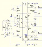
triple current-mirror
Triple current-mirror circuit:
Lets try something like this: SIM artists -- sharpen your pencils:
Thx-RNMarsh
View attachment CFA 3xmirror.pdf
Triple current-mirror circuit:
Lets try something like this: SIM artists -- sharpen your pencils:
Thx-RNMarsh
View attachment CFA 3xmirror.pdf
Speaking of good resistors .... a CFA needs good ones for the FB return.
Bob C's comment on the thermal issue has me worried 😕 .
http://www.irctt.com/file.aspx?product_id=36&file_type=datasheet
Would the 3W device above do the job ? My CFA's dissipate a little less current in
the FB network (1+W).
Are there any differences between thin/thick film ?
PS - A small drawback for CFA - special resistors ?? 😀
OS
3w of thin-film should be OK IMO
-RM
yus are all idiots & deaf
I queried this in #3472 and other posts.. His eventual reply is in #3473. which was less than helpful. 🙁
Reading between the lines, I think it is likely that he has simmed his own circuit but as he doesn't present his PSSR & THD results, there is no evidence. We have to take his word for it.
I think its unlikely he has simmed a version of your circuits for comparison but I might be wrong.
So at the moment, the 'improvements' are mythical unicorns 🙂
My naive visible inspections of his & your circuits suggest little or no 'improvement'.
________________
Waly, I'm not sure why you are participating in this thread. Most of us are either trying to help or be helped in our poor efforts to design better amps.
Why don't you join JC's blowtorch-preamplifier thread instead?
There presides the true master of 'yus are all idiots & deaf'. 😱
Blind Listening Tests are scorned. Only sighted tests by true afficianado's are allowed. Incredibly complex measurements are proposed but results are never revealed. If revealed, measurements & tests may instantly be declared heretical if they don't put Holy Devices in a good light.
I'm sure your undoubted talents will be given full reign in that 'hand carved by virgins from solid Unobtainium' environment and they will fully appreciate & applaud your knowledge, expertise & experience. 🙂
Us unwashed masses on this humble thread are unable to decipher your words .. naively assuming always that you meant to help us design better amps. 😱
Edmond, Waly posted a response to your #3135 circuits claiming 'improvements'.I know nothing about any 'improvement'. Did I missed something important and should I adjust my ignore list? 🙄
I queried this in #3472 and other posts.. His eventual reply is in #3473. which was less than helpful. 🙁
Reading between the lines, I think it is likely that he has simmed his own circuit but as he doesn't present his PSSR & THD results, there is no evidence. We have to take his word for it.
I think its unlikely he has simmed a version of your circuits for comparison but I might be wrong.
So at the moment, the 'improvements' are mythical unicorns 🙂
My naive visible inspections of his & your circuits suggest little or no 'improvement'.
________________
Waly, I'm not sure why you are participating in this thread. Most of us are either trying to help or be helped in our poor efforts to design better amps.
Why don't you join JC's blowtorch-preamplifier thread instead?
There presides the true master of 'yus are all idiots & deaf'. 😱
Blind Listening Tests are scorned. Only sighted tests by true afficianado's are allowed. Incredibly complex measurements are proposed but results are never revealed. If revealed, measurements & tests may instantly be declared heretical if they don't put Holy Devices in a good light.
I'm sure your undoubted talents will be given full reign in that 'hand carved by virgins from solid Unobtainium' environment and they will fully appreciate & applaud your knowledge, expertise & experience. 🙂
Us unwashed masses on this humble thread are unable to decipher your words .. naively assuming always that you meant to help us design better amps. 😱
Yes , I just dropped an output stage trick over at the "blowhard" thread.
Totally ignored the 20db PSSR improvement (driver RC "trick").
I'm no guru , CFA layout "seems" to be the same as VFA .. except for them
"fat" resistors.
I "floated" the output signal right to the feedback pair (silver wire with a 1K resistor
at the end 😀 ) ... no long traces.
Kept everything symmetrical like the VSSA.
Only a 2V feedback signal will ever touch the board. I was thinking "anally"
and did not want a 100v signal to come near any of my components.
OS
Attachments
Waly, I'm not sure why you are participating in this thread. Most of us are either trying to help or be helped in our poor efforts to design better amps.
I am having fun, does this compute? Or is this not allowed on a public forum?
For more details and simulations, I am waiting for the time when I'll be a retired beach bum. Meantime, my time is limited, and I don't appreciate being poked and summoned to contribute more every other post.
Speaking about contributing, I am patiently waiting to receive your own contribution to this CFA saga. So far, I haven't seen anything but peanut gallery and messages requesting people to work hard to do your homework in basic electronics.
If reading my posts is such a painful experience, may I suggest following other famous designers example and put me on your ignore list?
And because you asked, here's what I did today at work (not audio, of course): measuring the loop gain of a two pole compensated cmos op amp (a signal conditioning building block in one of my analog + DSP circuits). 3.6MHz ULGF, not bad for this process and slightly over 1mA Iq. About 45dB of loop gain to linearize. Ignore the LF (under 100KHz) phase, the scale is also wrong, should read 0 top -200 degrees bottom. For the final cut, I need to push the zero a little further in frequency to gain 10 degs of extra phase margin. BTW, I build the loop gain measurement jig myself.
Attachments
How do the commercial units handle it?
TADs M600 CFB amp uses carbon film resistors from Amtrans in the feedback.
Member
Joined 2009
Paid Member

The second plot in post #3118 is probably oscillating at many MHz at a low level (digital scopes s**k).
...This is why I hate DSO's the display artifacts make possible problems ambiguous.
I have a Philips 200 MHz analog scope and a Rigol. The Rigol 1 GS/s (IIRC) does a remarkable job of triggering in the presence of lots of phase noise. I was able to pick up a c. 180 MHz cascode problem on my e-Amp ...
I need to update my old, slow scope.
DSO seems the obvious choice and I had read Andrew's notes that confirmed the idea.
But a tool always has subtleties and practicalities that only show up after some experience and use, inevitably after one has already paid and it's too late.
So I am interested why the discrepancy between Andrew's comments and Scott's obviously valuable experience.
What display artefacts do I need to watch out for? I assume this is more than the obvious Nyquist sample frequency limitation.
Is there a phase noise tolerance metric or test?
Any further information would be appreciated, other people's experience too.
Best wishes
David.
Last edited:
Waly...
Why don't you join JC's blowtorch-preamplifier thread instead?
There presides the true master of 'yus are all idiots & deaf'. 😱
Blind Listening Tests are scorned. Only sighted tests by true afficianado's are allowed...
Don't want to be drawn into personal issues, but I would like to learn and that will be easier if the bitterness stops.
I do think your comment seriously misrepresents Waly, he may think there's lots of idiots but he seems to have annoyed people precisely because he demands proper tests to support the "CFAs sound better"/"More slew rate sounds better" claims.
And AFAIK absolutely no such tests have been provided as evidence.
So can the unsubstantiated claims stop so that Waly doesn't spend his efforts to dispute them?
Then perhaps he will have more time for more productive topics.
And at least the thread will have less noise.
Best wishes
David
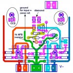
...kept everything symmetrical like the VSSA
Nice presentation of the layout, the colours really help to make it clear, service manuals should do it.
What did you use to create this?
Nice idea to make actual boards this way but most PCB fabs only do one colour silkscreen AFAIK.
Best wishes
David
Don't want to be drawn into personal issues, but I would like to learn and that will be easier if the bitterness stops.
I do think your comment seriously misrepresents Waly, he may think there's lots of idiots but he seems to have annoyed people precisely because he demands proper tests to support the "CFAs sound better"/"More slew rate sounds better" claims.
And AFAIK absolutely no such tests have been provided as evidence.
So can the unsubstantiated claims stop so that Waly doesn't spend his efforts to dispute them?
Then perhaps he will have more time for more productive topics.
And at least the thread will have less noise.
Best wishes
David
One will never get 'proper' tests to substantiate what they hear or perceive. Few want to do it. I think that for the decades of many people beside Waly asking for this type of input and not getting it... ought to know not to even ask.
I have used this concept before --- the drug industry --- they do double blind trials all the time only to find that when researchers later look at the huge amount of meta data and sift thru it, they often find such Accepted drug isn't working at all or in some other way or causing serious problems etc etc. It takes a huge amount of $$ and time to get the data right -- even after DBT have been done correctly. Even if it was done on a thousand people.... compared to the millions not tested, the drug test results can still be wrong. So, I try to err on the side that has the most people, from the widest range of cultures with a wide variety of equipment combinations and experience - saying the same thing over a long time period. To me THAT kind of information/data becomes the real truth.
Thx-RNMarsh
3w of thin-film should be OK IMO
-RM
Hi Richard,
Are you saying that you think it is OK to use a 3W resistor in a feedback network where that resistor is dissipating 1W?
Cheers,
Bob
0.05% for that junk is a real performance. I would think no sane person should build this in the year of 2014, but I'm pretty sure some would disagree 😀.
Mind you, it has absolutely none of the distortions cancelling and negative feedback VFA properties that I mentioned.
I was measured my VFA amp with real instrument at 11 years ago. The distortion is 0,06% near clipping 120W 8 Ohm. No matching device. I assume in 2014, amp design will be huge improve.
I wait LC's First One 😀.
.
It is true that a low slew rate can create distortions. Not said in the ad: you don't need a CFA to reach the point of no slew induced distortions. As I already mentioned, 1V/uS for each peak output volt is more than enough.
I mentioned the TPA6120 CFA as an example of (low power) application where CFAs are at par with the best VFAs, and where an attempt to build a discrete version, VFA or CFA, doesn't make much sense. Mind you, the topic is power amplifiers, and don't make me start ranting again about the VSSA.
1V/uS for each peak output is good enough for your ears, not my ears. Absolutely, your ears and my ears is different. I know the different how my VFA amp with 0,06% THD sounding againts VSSA.
The need of 1V/uS for each peak output is marketing only 😀.
I am sure you don't know how VSSA sounding, may be you just try VSSA in simulation (but I doubt that).
Hi Richard,
Are you saying that you think it is OK to use a 3W resistor in a feedback network where that resistor is dissipating 1W?
Cheers,
Bob
 Hi Bob,
Something like that. Why do you ask?
It is sort of minimal and would like to see 5W.
-Richard
Hi Richard,
Are you saying that you think it is OK to use a 3W resistor in a feedback network where that resistor is dissipating 1W?
Cheers,
Bob
Would it not ? ... the TCR of that series of IRC resistor is 50ppm/W.
Also , it derates to 2W at 70C. Should I double up on them ?
(2 x 100R + 2 x 2.7K gives about the same gain).
By Dave Zan -Nice presentation of the layout, the colours really help to make it clear, service manuals should do it.
What did you use to create this?
Sprint 5.0 > paintshop pro (PSP) negative image> solid fill the traces.
I do all my layout in my head - no CAD assist in component/trace placement.
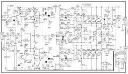
I found my AMP !! Real close ... A NAD 372 (below 1). I added it's "CFA core"
(NAD calls it "current feedback" , as well) , to my circuit.
It works (almost) as good in the slew/THD arena. But it Sucks PSRR wise ...
that's why NAD HAD to use a boosted supply.
They cascoded the FB stage and referenced the diamond to it ...just to save
a few parts (CCS's) ... Booooo !! 🙄
The NAD then runs it's Hawksford at 20ma to run a diamond driven
CFP OPS !!
I was relieved to see my capacitor DC reference and the trimmed hawksford
as DC adjust ... I'm on the right track !
But , I beat the NAD for THD20 - slew , and definitely PSSR. 😀
Marantz has a couple of CFA offerings as well (simulated them and also won).
My amp is just a little updated , NAD and Marantz had a few good "tricks" -
(below 2).
OS
Attachments
- Home
- Amplifiers
- Solid State
- CFA Topology Audio Amplifiers