listening experience of such a classA amp?
You'll have to visit the PL forum for that, SoZ, Zen variations, balanced Zen, etc. ,for most of the early Zen experimenters it's been at least a decade ago.
Balanced operation degrades SE to an extent, that it does not justify the rotten efficiency, imo.
My preference is fully balanced class A PP, with single supply regulated rails.
(one thing I'd still like to endeavour is a balanced Glen Kleinschmidt A+ , with at least cap multipliers for both the low and high voltage level rails)
jacco, is that the amp that was a variation on the Japanese (Panasonic?) where the little Class A amp floats on the large Class B amp?
Anatoliy, very interesting... you constantly surprise me!
Might you have real world scope shots of that circuit clipping?
Seems like you have made me have to stare at your schematic for a while.
Araxalito, the big problem with the CCS or whatever loading the "other side" of the SE output stage is the nil PSRR. So getting the residual out isn't so easy.
Bigun, not sure why one can't adjust the bias for AB operation on the JLH amp, worst case I'd guess that you'd alter the vbe multiplier or something along those lines?
Anatoliy, very interesting... you constantly surprise me!
Might you have real world scope shots of that circuit clipping?
Seems like you have made me have to stare at your schematic for a while.
I did not have digital camera back in late 70'Th, sorry. 🙂
But you can imagine how it looks when a voltage follower gradually turns into current amplifier. Similarly to like 6L6 push-pull output stage starts saturating, feedback ratio gradually is lower and lower, until you see pentode output without negative feedback.
Last edited:
balanced/bridged output with push-pull Class A works just fine with 50% max efficency - and the ps current draw is constant too
not that I get very excited by constant current draw from a standard diode-cap linear supply which already must deal with ~10x pk vs ave charging current pulses at 2x mains frequency
not that I get very excited by constant current draw from a standard diode-cap linear supply which already must deal with ~10x pk vs ave charging current pulses at 2x mains frequency
Last edited:
How do you get 50% max efficiency and ps current constant too? Got any schematic references for this as it could be wonderful news for me - saving on my next build - if true.
I left behind standard unregulated linear supplies quite some time ago, so I agree.
<edit> I've seen choke loaded classA get 50% efficiency but is that going to be ps invariant?
I left behind standard unregulated linear supplies quite some time ago, so I agree.
<edit> I've seen choke loaded classA get 50% efficiency but is that going to be ps invariant?
Last edited:
the sum of the Class A push-pull drives for the 2 sides in bridged drive is ideally constant
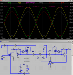
over complicated to illustrate the point, but shows monolithic op amps biased Class A push-pull too
~ +/- 80 mA to load&feedback R with ~4 mA 2nd harmonic AC out of ~ 126 mA constant power draw:
over complicated to illustrate the point, but shows monolithic op amps biased Class A push-pull too
~ +/- 80 mA to load&feedback R with ~4 mA 2nd harmonic AC out of ~ 126 mA constant power draw:
Attachments
Last edited:
An interesting option, which I like but can't run Class AB (only A), is the JLH 1969 Class A 10W.
Also look at Look up Hiraga Class A 30W, or PASS F5.
Also Musical Fidelity A-1
for a further interesting spin
I ran the transient sim. 4V peak each side into the 120R load gives 267mW output power. Total current drawn from 24V supply around 115mA giving 2.76W. Efficiency 10.7%. I then doubled the output power (source increased from 1V to 1.41V) but then the current from the supply varied considerably (more than 10%). At this point the efficiency's still under 25%.
Some error in my math?
Some error in my math?
50% is ideal Class A push-pull efficency - not allowing for Vdrop, no current for the rest of the circuit
and exact load match to Vsuppy, bias I
the op amps have >1 Vdrop from each rail and high quiescent current - not all is avialable to the ouptut
the currrent sharing R are too high Value too - adds another 1 V to drop
and exact load match to Vsuppy, bias I
the op amps have >1 Vdrop from each rail and high quiescent current - not all is avialable to the ouptut
the currrent sharing R are too high Value too - adds another 1 V to drop
Last edited:
I'm aware of all those factors - the specific claim that was interesting to me was :
balanced/bridged output with push-pull Class A works just fine with 50% max efficency - and the ps current draw is constant too
but it turns out your circuit doesn't deliver according to the claim. Upping the output drive level gives better efficiency but loses the invariant current feature. So far I've seen nowhere near 50% efficiency together with invariant current draw. Either as supplied in your sim 11% efficiency with almost (say <5%) invariant current draw, or better efficiency without ps invariance. So am I missing something vital or is it just your claim was overblown?
Probably 50% at maximum output swing while lowering balance resistors to approach 0R and R-R amps.
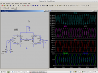
Here's a very simple class A balanced output stage, reproducing a 1000 Hz sine. The load is a current source at 1100 Hz. This exercises all quadrants of the output stage like a loudspeaker does (and a resistor does not).
Anyway, power supply current variations are much smaller than load current variations. This would get better with a more linear output stage like CFP.
I don't know if the effect is really useful, although for small signal stages, it would make the regulator's job easier... for a poweramp, I dunno... it would make the noise generated by the rectifier diodes and the supply ripple more constant (less signal-dependent), that would probbly be a good thing, same if a switching PSU is used... also, less stray magnetic fields from wires, and having only one power supply makes things simpler, max dissipation in the output transistors is 2x less, but you need a lot more of them... I never listened to such an amp, could be an interesting concept...
Attachments
Last edited:
Probably 50% at maximum output swing while lowering balance resistors to approach 0R and R-R amps.
Yes, quite probably so. I've lowered the balance resistors to 2ohms, it swings 1W (16V peak to peak) but the load current is far from being invariant - and the efficiency reaches around 30%.
So it looks like we can have constant draw at 25% max efficiency, or approach 50% efficiency and variable current draw but not both. Which was what I had assumed was the case prior to playing with this circuit 😎
So it looks like we can have constant draw at 25% max efficiency, or approach 50% efficiency and variable current draw but not both. Which was what I had assumed was the case prior to playing with this circuit 😎
Have a look a the MF A1 - a rather different circuit
abraxalito, look at my post above.
The ratio of [max class A power to load] to [idle losses] is much more interesting than efficiency, unless the amp is only used to drive full power sinewaves all the time (or the current loudness wars record winner CD...)
With music having a good dynamic range, the amp will rarely actually output a significant amount of power... so who cares about full power efficiency ?
Case #1
Split supply amp : +/- Vcc supply
Push pull class A with emitter resistors
Idle Bias Current : IBias
Let Iload = current in load
The output will stay in class A (both transistors on) up to |Iload| < 2*IBias
If the bias is high enough, the amp will operate in Class A up to clipping.
Let's suppose the clipping voltage is +/- Vcc...
Split
Idle power dissipation = Vcc * 2*IBias
Max Class A power to matched resistive load = Vcc * 2*IBias
Current draw on supplies : each has IBias (DC) +/- ILoad/2 (AC).
At the limit of class A, then, the current in one supply is 0 and the other is ILoad=2*IBias...
Case #2
Single supply amp : +Vcc supply only
Bridged (balanced) Push pull class A with emitter resistors
Idle Bias Current : IBias (same on each side of the bridge)
Same as above :
Let Iload = current in load
The output will stay in class A (both transistors on) up to |Iload| < 2*IBias
If the bias is high enough, the amp will operate in Class A up to clipping.
Let's suppose the clipping voltage is Vcc...
Now :
Idle power dissipation = Vcc * 2*IBias (total of both sides of the bridge)
Max Class A power to matched resistive load = Vcc * 2*IBias (same as above !)
Current draw on supplies : IBias*2, constant (first-order).
There is no efficiency diifference between the two... idle losses are the same and max class A output power is the same too. Dissipation is also the same but it is split between the two half bridges...
Both also have the same current draw on the supply, since the sum of the V+/v- currents in the split supply amp is ... the same as the bridged amp supply current...
If we look from a different perspective - achieving a good sound - we will see that for different people "good sound" definition is different.
In the article about Musicle Fidelity A1, mentioned here by thoglette, there is an expression I like a lot:
"The long tailed pairs are not fed from a current source, but the tail resistor is fed from a zener-regulated rail which prevents power supply noise reaching the LTPs. Each of the LTPs is unbalanced, meaning that the collector currents in each half of each pair are unequal. Maintaining equal collector currents with a current mirror or similar will provide the cancellation of second-harmonic distortion that is possible with a long-tail pair, but it's an option frequently eschewed by designers - mostly on cost grounds, but also perhaps because mild 2nd order distortion can sound "nice" subjectively."
Some people like 2-nd harmonic to be there. It is actually much easier to achieve technically, than if you don't want it to be there.
Now, class A. Let's look at it as at evolution.
1) Easiest output setup - collector with high idle current loaded by a resistor.
2) Want more linearity - change resistor to current source.
3) Want more power efficiency - make the current source controlled by the input signal (and you get push-pull).
Posible artefacts will be eliminated by appropriate NFB (sorry for mentioning it in class A thread 😀 well, just joking).
Ideal amplifier - zero power consumption, zero distortion, infinite power.
The design very much depends on what you want to achieve. I personally like "transparent" amps. But do I want to live with idle current 4-5 A? I'm really not sure... 🙄

- Status
- Not open for further replies.
- Home
- Amplifiers
- Solid State
- Push-Pull vs. Single-Ended in Class A Operation