Hiya guys new amp project with solid state rectification.
power tranny has a 5volt@ 3amp winding for rectifier, that is unused question is...
What should we use it for ? what little extra would you throw in to use it?
suggestions please no matter how frivolous they may be..😛
power tranny has a 5volt@ 3amp winding for rectifier, that is unused question is...
What should we use it for ? what little extra would you throw in to use it?
suggestions please no matter how frivolous they may be..😛
Voltage doubler into a LM7809 or better to power a stomp box?
Got a diagram? coz that is a useful idea.🙂
Not to hand, but I can put one together and post it when I have some spare time if someone else doesn't beat me to it. 😀
Voltage doubler into a LM7809 or better to power a stomp box?
This is a great idea! I would probably use a SEPIC device to boost right from 5V to 9V efficiently. You could likely get an evaluation board from Linear Tech for fairly cheap and wire it right in.
It depends on the main use for the original project.
Yes, of course. Do you have some examples?
In my previous project I used it as a relay supply for channel switching.
original project is a harmonica amp. and yes harp players DO use stomp boxs, the main one i use is a digital delay , very power hungery baout 15 to 20 minutes on a 9volt batt.
also any other suggestions will not be laughed at.
It just goes against the grain to not use a perfectly good 5 volt winding.
It just goes against the grain to not use a perfectly good 5 volt winding.
I'd rectify & "cap" it to drive a 12VDC four inch cooling fan at 60%...to keep it super quiet.
_______________________________________Rick......................
_______________________________________Rick......................
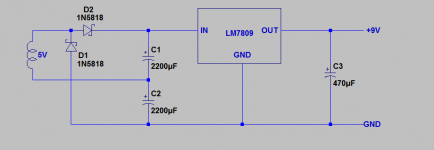
Here is the stomp box PSU circuit I promised, just six parts and a small heat sink. Get the parts from Digikey or Mouser. Don't ground the supply, let it float - let the stomp box provide the sole ground reference to avoid ground loops. Capacitors can all be 16V..
Attachments
If it is a solid state amp, I would use the extra 5 v winding to produce 6 VDC to power a speaker disconnect circuit. The Michael Bean source to source FET circuit can connect speakers using a photovoltaic optoisolator to drive them, but the logic to drive all that could be separated from the main audio power supplies for less digital noise. Otherwise there might be a pop when the turnon delay circuit times out which forces the FETs to the on state.
I put a little wall socket transformer in my pv-1.3k to power the dc overvoltage detectioin to FET shutoff circuitry. The 74HC74 flip flops required a 4.5 to 6 v power supply, and it takes an IC that powerful to take 0.1 ma from optoisolator phototransistors relaying the overvoltage detection, and source 2.5 ma to drive an ordinary transistor base to produce 10 ma to drive the photovoltaic fet drivers.
I stacked up the two fet driver LED's, plus a series green LED on the front panel, plus the driver transistor c to e, to require a minimum of 5.8 v to get the leds to turn the fet drivers to turn on in the no-fault state.
With all that, I'm using about 21 ma total for the LED's and drivers for both channels. There is a red/green LED indicator for each channel, held face up to the vents in the front of the amp. One hole drilled for all 4 LED's, a 4-40 clearance hole, and a mount board with both fault LED's.
Last edited:
A good trick I stole from Gingertube, put the 5V and 6.3V filament windings in series, and run the filaments on 12V - lower current = less noise.
You don't have to do anything with it! It is a low voltage winding, so it won't come to any harm if you don't connect it to anything. As others have said, you could use it to power a pilot light or an external module of some kind.
Personally, I would use it to power a GZ34 rectifier valve, as the high HT voltage at switch on [when using solid state rectifiers] can damage the cathodes on output valves.
Even if you want to retain your solid state rectifier you could still connect a valve rectifier in the circuit so that HT voltage is applied gently when the other valves have warmed up.
Yet another idea would be to use it to power a fixed grid circuit, but you really need a much higher voltage for it to be of any use.
Most of the good ideas have been taken...
Buck or boost winding in series with the primary to correct any small differences in line voltage.
Buck or boost winding in series with the primary to correct any small differences in line voltage.
Yet another idea would be to use it to power a fixed grid circuit, but you really need a much higher voltage for it to be of any use.
It could be used for fixed bias on the preamp triodes. Has anyone fixed bias preamp stages in a guitar amp? I would guess it's only useful for the first stage, or for reverb/vibrato circuits. In overdrive stages you'll want to control the gain shape with Ck and get the compression effect of cathode bias.
Thanks for the tips!
My next build's got an unused 5v@3A winding and never thought about adding a 9v supply to power external pedals. It's a great idea!
My next build's got an unused 5v@3A winding and never thought about adding a 9v supply to power external pedals. It's a great idea!
Schottky diode bridge rectifier into 10,000uF will give you right on 5.95V DC when
powering a couple of 12AX7 heaters( 0.6 Amps).
Cheers,
Ian
powering a couple of 12AX7 heaters( 0.6 Amps).
Cheers,
Ian
- Status
- Not open for further replies.
- Home
- Live Sound
- Instruments and Amps
- What would YOU do with an xtra 5v winding