Just to confirm the reg. section must be wired to the audio section right?
Do you have an estimate for the cost for the boards?
Do you have an estimate for the cost for the boards?
Hi juma,
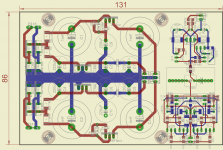
Just new to this thread and on post #66, you have a power supply diagram that has 4 x 220uF electro caps in series with the secondary windings, before the diodes (double bridges) - could you possibly expand on this a bit, as I've not seen this before and quite puzzled about the use of them.
I use 4,700uF electros for mains supply 'dc traps', but puzzled about the 220uF ones.
Actually, voltage is not being doubled in that PSU (post #66) - it's just the same secondary (~36V CT) being used twice (through C1-C4) to create positive and negative rail (re. to CT=GND) out of the same voltage source.
Have in mind that reactive resistance of the capacitor (Xc) is reversely proportional to its capacity and frequency of the AC voltage, so where higher current is needed use larger value caps.
Have in mind that reactive resistance of the capacitor (Xc) is reversely proportional to its capacity and frequency of the AC voltage, so where higher current is needed use larger value caps.
Sorry juma, having a 'brain fade' here!
The supply obvious works quite well (working version) but I'm a bit puzzled at the inclusion of the caps C1 - 4 between the secondary winding and the diode bridge - please excuse the dumb question, it is Xmas eve ....
If the +33 volt rail (for example) is supplying 50mA to the circuit, there's a voltage loss of about 4.5 volts across the IRF610 fet C multiplier, and another 5 volts across the 100R resistor, so raw supply has to be about 43 volts out of the diodes, if I've got this far okay?
So, if the full bridge produces somewhere near 48 volts from the 36 volt secondary (?), minus 1 volt (maybe) across the bridge, then where does the missing 5 volts go?
There's a nice Christmas mystery for you to solve - build it, test it. It won't cost you much and is a lot of fun! 😉...where does the missing 5 volts go?
Those are approximate values. It depends on parts you use - not all 10VA/~36V CT transformers behave the same way under load. Diodes and caps too. Maybe you'll have to use 150R instead of 100R. Those things are trivial - with little effort you should be able to adjust such a circuit to your needs, no matter what specific parts you got...
If dsired, I can look into getting the majority of the smd parts presoldered to save trouble. I am unsure of the cost. Just an idea as some are a bit intimidated by the process. I should be able to buy and match the BF862 with a tracer. You will have to take care of the jfets. I am going to start a thread in GB section as I do not want to clutter this thread. I am not wanting a big run her. Want to keep it simple so this may make the pre-mount idea a no go, just thought I would mention it.
juma's pre
If dsired, I can look into getting the majority of the smd parts presoldered to save trouble. I am unsure of the cost.
GREAT IDEA......You should see that iron shake in my 80 yr old mitts....
At my age I have no option to want as much as possible pre-soldered!! YES PLEASE BUZ .........This will help to make Christmas less troubed as I will have fewer fiddly things to do in 2014!!
Have a great Holiday all of you!
Have a great Holiday all of you!
Happy holidays to all as well. Ill post in GB forum with final options and we will go from there. Thanks to Juma for the work.
It's not much of a work, fun mostly - thanks to Mr. Pass for bringing this great circuit back to life !
Marry Christmas everyone !
Marry Christmas everyone !

- Home
- Amplifiers
- Pass Labs
- LSK pre - BAF 2013