I need a circuit that can help me match Jfets to a specific current range of Idss 4-6ma and another circuit than can match them for gate source voltage. Can anyone point out a circuit that can do so. Thanks
I hope that Nelson has shown how to do this, BUT it is fairly easy with just a multimeter. You just short the gate to the source and add a 9V battery from the drain to the source. This gives you Idss. But how to measure? Put a 10 ohm resistor between the drain and the battery and measure across it. 0.1V=10ma and so forth. Matching Vbe is much more difficult.
DMM
I use a multimeter set on 200 mA caliber and short grid to source...
I then take a sheet of paper, mark a scale from (for instance) 15 to 40 mA, and drop the transistors on the scale after measuring them. That's an easy way to group them without headaches...
I use a multimeter set on 200 mA caliber and short grid to source...
I then take a sheet of paper, mark a scale from (for instance) 15 to 40 mA, and drop the transistors on the scale after measuring them. That's an easy way to group them without headaches...
Re: DMM
Can you recommend good JFETs in the 15-40mA range? How many would it take to find 4 that match at around 20mA? Is 10% considered an adequate match? And how much better would 2% matches be???
What I have in mind is matching 4 JFETs for the outputs to a headphone amplifier (for 300 ohm Sennheisers). I'm thinking about 2sk170, but don't know if I would need to buy 20, 50 or a 100 (to find enough that "match").
Sorry for a barrage of questions (I don't know if someone is reading that knows such things "like the back of their hand"). TIA.
JF
peufeu said:I then take a sheet of paper, mark a scale from (for instance) 15 to 40 mA, and drop the transistors...
Can you recommend good JFETs in the 15-40mA range? How many would it take to find 4 that match at around 20mA? Is 10% considered an adequate match? And how much better would 2% matches be???
What I have in mind is matching 4 JFETs for the outputs to a headphone amplifier (for 300 ohm Sennheisers). I'm thinking about 2sk170, but don't know if I would need to buy 20, 50 or a 100 (to find enough that "match").
Sorry for a barrage of questions (I don't know if someone is reading that knows such things "like the back of their hand"). TIA.
JF
JFETs
I have only used JFETs to cascode bipolars so can't comment directly on their sound qualities.
I have used J309 in my DAC and that works well (and is cheap, too).
I think J309 would fit your bill, maybe. Look at the IDss values...
I have only used JFETs to cascode bipolars so can't comment directly on their sound qualities.
I have used J309 in my DAC and that works well (and is cheap, too).
I think J309 would fit your bill, maybe. Look at the IDss values...
Re: JFETs
: )
JF
peufeu said:I have only used JFETs to cascode bipolars so can't comment directly on their sound qualities.
I have used J309 in my DAC and that works well (and is cheap, too).
I think J309 would fit your bill, maybe. Look at the IDss values...
: )
JF
2SK170s........
If you really need that much current, assuming that you have the BL group, you can put 4 in parallel to get that amount of current. Maybe with 3, but 4 to be certain.
Jocko
If you really need that much current, assuming that you have the BL group, you can put 4 in parallel to get that amount of current. Maybe with 3, but 4 to be certain.
Jocko
Hi,
Current sharing resistors not included? Or are they?
Cheers,😉
you can put 4 in parallel to get that amount of current. Maybe with 3, but 4 to be certain.
Current sharing resistors not included? Or are they?
Cheers,😉
What comes closest to what I have in mind is Borbely's "Super Buffer" which is figure 8 at the following link:
http://www.borbelyaudio.com/borb502.pdf
I'm thinking of parallelling 4, 5, 6...or whatever of the jsk170/jsk74 to get 100mA. It seems that violet parts would help me get there at a lower part count (and are just a little more cost). Maybe you're suggesting 5 ohm series resistors to allow for differences between JFETs. Figure 9 shows a MOSFET version (with higher current output), but Borbely suggests that an all JFET amplifier would be the best.
My question is how closely matched (10, 5, 2%) do the k170/j74 pairs need to be?
JF
I have a bunch of 2N3819 JFETs with Vp from -1.3 to -2.97V.
How well do they need to be matched for a differential front end?
Also gathering 2SK170'BL's. How much variance are there and how much can I tolerate when paralleling 4 of them?
Tom
EE
How well do they need to be matched for a differential front end?
Also gathering 2SK170'BL's. How much variance are there and how much can I tolerate when paralleling 4 of them?
Tom
EE
I hope that Nelson has shown how to do this, BUT it is fairly easy with just a multimeter. You just short the gate to the source and add a 9V battery from the drain to the source. This gives you Idss. But how to measure? Put a 10 ohm resistor between the drain and the battery and measure across it. 0.1V=10ma and so forth. Matching Vbe is much more difficult.
Following this guide looking at the datasheet for 2sk170bl - 0,00v over 10 Ohms... Tried 4 of them now. Maybe the battery is old. Even moved everything down my experiment board - no dice...
Regards
Following this guide looking at the datasheet for 2sk170bl - 0,00v over 10 Ohms... Tried 4 of them now. Maybe the battery is old. Even moved everything down my experiment board - no dice...
Regards
Battery broken...
Regards
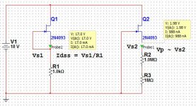
The Nelson Pass page with explanations and diagrams is "Matching Devices" at https://www.passdiy.com/project/articles/matching-devicesI hope that Nelson has shown how to do this, BUT it is fairly easy with just a multimeter. You just short the gate to the source and add a 9V battery from the drain to the source. This gives you Idss. But how to measure? Put a 10 ohm resistor between the drain and the battery and measure across it. 0.1V=10ma and so forth. Matching Vbe is much more difficult.
My atch diagram is taken from a circuit simulator (Multisim) but illustrates the concepts.
Dale
Attachments
When checking for Idss, how long is the jfet left in the circuit and when is the measurement taken? Is it first few seconds or after 1 minute or until the jfet reaches a certain temp?
thanks,
Vince
thanks,
Vince
Measure it at the quickest timing possible, as the temperature rise is dependent on the Idss which you have quite a variation in the lot.
Last edited:
You can pretty much measure everything with a DMM and a sound card :
FET Measurements with Just A DMM
Patrick
FET Measurements with Just A DMM
Patrick
- Status
- Not open for further replies.
- Home
- Amplifiers
- Solid State
- Matching Jfets