On paper that Visaton looks good but I have no clue about the sound quality.
I would suggest this one instead - Dayton Audio DA175-8 7" Aluminum Cone Woofer | 295-335. Its specs give it a similar response to the Visaton and it has very decent distortion measurements for the price.
See the 1st product review of the Dayton down lower on the above link - most informative for you I think. And see Zaph|Audio too to see how the driver stacks up against others (although much of what he says may be too technical for you, it's a great sight for learning - there are a lot more pages than just that one).
Ok, I'm still going to build my 55L cabinets for the MCM's and try them out but I'll order two of those DA175's. Does not seem to be much talk about he Visaton. Will the lower 85db sensitivity of those be a concern for me?
I have to say I have been listening to my MCM speaker in the too small box with the "parts on hand" crossover. The only other speaker I have in the house that was purchased is an old set of Realistic Nova 4's ( 2 way 8" reflex) and I know their nothing great and I never liked them but they were buy one get one free. As is, the MCM speaker pounds, punches and takes anything I dish out at it. The Nova thumps a little, balks at high power and sometimes makes strange plopping noises and overall even at low volume just does not sound pleasing. Am I wrong in assuming that once the MCM's are in a bigger box and have a more appropriate crossover they will sound even better?
Thanks for that Zaph|Audio Link
Tony
Last edited:
Tony, if you place a PE order, fill the cart to $100 - free ship: woofers are heavy so can save there (vs. ordering from other sites). Think tweeters, coils/caps/resistors, damping material, black screws... Don't forget the coupon codes that can easily be found on the web.
Ah, you guys got me all figured out here - that I'm hooked now and going to buy all kinds of extra stuff. That's just what I planned on doing.😀
Tony
Ok, I'm still going to build my 55L cabinets for the MCM's and try them out but I'll order two of those DA175's. Will the lower 85db sensitivity of those be a concern for me?
Depends. How much power do you have, how big is your room and how loud do you like to play them? The amount of travel on these is about twice as much as the MCM's but still only about 4mm. Personally, I would probably want to use 2 of these together if I wanted to play them quite loud (but could probably also be happy with just 1 of them). But that box with 2 of them will be too big for you (and if you run them in parallel you want to be sure that your amp will be happy with a 4ohm load). If you don't mind stepping up another notch the next driver I would suggest for you is something ODougbo mentioned way back on page 2 - the Exodus Anarchy. This is a pretty special 6.5" driver about the same sensitivity as the Dayton but with almost 3 times as much cone travel available and needing about half the box volume to reach near the same bass output. Twice as expensive though.
Denovo Audio Anarchy woofer DIY Sound Group
Am I wrong in assuming that once the MCM's are in a bigger box and have a more appropriate crossover they will sound even better?
That's probably a fair assumption but the trick is going to be getting "a more appropriate xo". It's not quite as easy as it sounds without measuring the darn thing. Because here's the problem with an inexpensive driver like the MCM - it's difficult to know which measurements you can rely on. Note that MCM doesn't provide graphs with its drivers. There's probably a reason for that.
Just out of curiosity, I emailed them and they did send me their measurements (see below, 1st graph), but I can't make heads or tails out of the impedance measurement. A nominal 8ohm driver with an Re of 6.8 shouldn't have a minimal impedance down around 4ohm? Maybe I'm reading the graph wrong. It's a bit of a mess. The FR is also fairly different than what Steve posted back on page 1 which was done by Adire audio I think (2nd graph below). Here are the specs Adire came up with which are also different from MCM's specs:
Fs = 47Hz
Qms = 4.3
Qes = .42
Qts = .38
Vas = 26L
Box size and F3 ends up a little different with these numbers. I'm at a bit of a loss now in terms of making suggestions for them because I don't know exactly how the drivers you have in your hands are going to actually measure. Still, going with Steve's suggestion for a xo would seem best at this point.
That's another advantage of going with a more consistent brand like Dayton for example and especially of having a reliable 3rd party measure them like Zaph. Those measurements I can rely on and use to come up with a reasonably accurate simulation for a xo without having to measure them personally.
Attachments
Depends. How much power do you have, how big is your room and how loud do you like to play them? The amount of travel on these is about twice as much as the MCM's but still only about 4mm. Personally, I would probably want to use 2 of these together if I wanted to play them quite loud (but could probably also be happy with just 1 of them). But that box with 2 of them will be too big for you (and if you run them in parallel you want to be sure that your amp will be happy with a 4ohm load).
............................
That's another advantage of going with a more consistent brand like Dayton for example and especially of having a reliable 3rd party measure them like Zaph. Those measurements I can rely on and use to come up with a reasonably accurate simulation for a xo without having to measure them personally.
I really appreciate everything everyone here has done for me. You guys bent over backwards for me and I learned a lot. I'm going to ditch the MCM's
I rarely play music loud but now and then I love to hear some punch. My receiver is rated 125W at 6 ohms. I am going to order the Dayton DA175's based on the following:
1 - you guys recommended it.
2 - its got good reviews
3 - they say its easy to cross
I am going to build my boxes as planned at around 55L to 60L (approx 2 to 2.1 cu ft). For the DA175"s I'll have a somehow removable internal partition to bring it down to the recommended 1.2 cu ft. If I think their not loud enough (which I probably won't) I'll just order two more DA175's and make a new baffle and remove the partition, make changes to the XO and have an MTM.
The only question that remains is - When I order the DA175's should I order another vifa BC25SC06-04 tweeter since I already have one?
This is harder than I ever imagined but fun.
Tony
Hey Tony, it's xmas and you seemed to be having such a frustrating time there in the beginning.
Don't throw the MCM's out or anything. If you get to the point where you can do some measurements some day, you might want to do something with them. They appear to make pretty good sound for what you pay for them.
Play around with your box program a little more for the DA175 - a single does quite well in your intended size box but use the specs that Zaph has actually measured, here - Zaph|Audio. (Choose the DA175-8 and then the Thiele/Small Parameters)
For your purposes, I can't see any reason not use that tweeter. It seems like you already like its sound.
There is a lot more to speaker building than most people probably think, and there are definitely a number of different 'camps' that people approach it from but it's not exactly rocket science. What will help you now is to continue to experiment and design while reading as much as you are able. sreten linked to a lot of good sites back on page 1 to help you out.
I'd suggest going to this 1 next,
The Speaker Building Bible
and working your way through as far as seems necessary for you. Some of the links are dead and some of the stuff you may already know but if you can get to the simulation and then the measurement stage you'll probably be pretty happy with yourself. Oh, and have some pretty good speakers too.
Maybe if I can find the time, I'll see what a simulation of the Dayton and the Vifa look like.
Cheers
Hey Tony, it's xmas and you seemed to be having such a frustrating time there in the beginning.
Play around with your box program a little more for the DA175 - a single does quite well in your intended size box but use the specs that Zaph has actually measured, here - Zaph|Audio. (Choose the DA175-8 and then the Thiele/Small Parameters)
Maybe if I can find the time, I'll see what a simulation of the Dayton and the Vifa look like.
Cheers
Thanks for that link. I'll never make sense of those response curves. I would think the better speakers would have little or no ups and downs and jaggedness but in my eyes some seem to have more ups and downs.😕


Tony
Thanks for that link. I'll never make sense of those response curves. I would think the better speakers would have little or no ups and downs and jaggedness but in my eyes some seem to have more ups and downs.😕
Tony
No, you're right. The best speakers will have a flatter response (more or less). But it's the xo that does the work to flatten everything out. The raw driver's FR can often be far from flat but what you are trying to look for is a fairly flat response in the frequencies that you intend to use it in (or the passband). Because the junk that may be happening above or below the xo won't be as loud, the xo will force it to drop in SPL at a certain rate depending the parts you choose to use. But yes, a driver will be easier to work with (and usually cheaper, ie. less xo parts) if it's fairly flat to start off with.
Take the DA175 (1st graph). Putting it in a ported box will bring the bottom end up to about 35-40Hz. It starts dropping at about 1500Hz so somewhere around 2000-3000Hz would be a good place to xo to the tweeter. That junk up above 4000Hz will therefore be dropping in SPL and won't be heard as much.
If you look at the 2nd chart below, you should see that that peaking around 7000-8000Hz has a nasty resonance (circled area) and so we might want to do a little something extra to make sure that that doesn't receive very much signal. That's actually really easy to do by adding a small value capacitor in parallel with the woofer's inductor. I happen to be working on it right now so the 3rd graph shows you the result with a simple 3 component xo (the dark blue is the raw FR that includes baffle step loss and diffraction). And then the 4th graph is just what I've come up with so far. All together it's pretty flat (black line) but I think the xo point is a little low so I'm going to try again and see what I can do.
Attachments
No, you're right. The best speakers will have a flatter response (more or less). But it's the xo that does the work to flatten everything out. The raw driver's FR can often be far from flat but what you are trying to look for is a fairly flat response in the frequencies that you intend to use it in (or the passband). Because the junk that may be happening above or below the xo won't be as loud, the xo will force it to drop in SPL at a certain rate depending the parts you choose to use. But yes, a driver will be easier to work with (and usually cheaper, ie. less xo parts) if it's fairly flat to start off with.
Take the DA175 (1st graph). Putting it in a ported box will bring the bottom end up to about 35-40Hz. It starts dropping at about 1500Hz so somewhere around 2000-3000Hz would be a good place to xo to the tweeter. That junk up above 4000Hz will therefore be dropping in SPL and won't be heard as much.
If you look at the 2nd chart below, you should see that that peaking around 7000-8000Hz has a nasty resonance (circled area) and so we might want to do a little something extra to make sure that that doesn't receive very much signal. That's actually really easy to do by adding a small value capacitor in parallel with the woofer's inductor. I happen to be working on it right now so the 3rd graph shows you the result with a simple 3 component xo (the dark blue is the raw FR that includes baffle step loss and diffraction). And then the 4th graph is just what I've come up with so far. All together it's pretty flat (black line) but I think the xo point is a little low so I'm going to try again and see what I can do.
I just ordered two DA175's and another Vifa tweeter. Got free shipping and $5 off from a previous order.
I'm going to build two boxes at 2 cu ft (but partitioned down to 1.2 cu ft for the DA175's) and 3 baffles - two for the DA175's and one for the MCM 55-1170. For educational purposes I think the MCM's are worth a quick listen to in a large box.
I'll never understand those mountain side graphs (the colorful ones with all the wavy lines of different colors).
As a side note - I work as an electronic engineer. I design complex data acquisition and and control systems involving processor chips, A-D and D-A Converters etc. I write software for these designs involving PID control and such. I only made it through one year of college and quit. A teacher at said college, who was a friend of my mothers, told her that I could teach him a few things. It all came easy to me. But this ###@@$%$%#$# speaker crap just totally baffles me. I've never been so challenged before.
Thanks for your help
Tony
Tony might be good to start a new thread like:
Dayton DA175-8 & xxxx Vifa Tweeter
For prosperity and remember, somebody might look for a project someday using that woofer and they'll find the thread.
Looks like you are on track now, maybe some others will jump in an build a set 🙄
Dayton DA175-8 & xxxx Vifa Tweeter
For prosperity and remember, somebody might look for a project someday using that woofer and they'll find the thread.
Looks like you are on track now, maybe some others will jump in an build a set 🙄
So Tony here is a little xmas gift.
My 2nd go at the simulation turned out nicely. I included baffle step loss of 4dB and the baffle diffraction effects of a 9.5" x 34" front baffle with a 1/2" roundover. The middle of the tweeter is placed 2.25" below the top of the speaker and the middle of the woofer 8" below the top. Both are centered on the baffle and you should stay fairly close to these parameters for the xo I've come up with. You can choose whatever tuning you wish. I chose a box volume of 55L with an Fb of 33Hz for this sim.
Both networks are 2nd order electrical (1 inductor and 1 capacitor each). The woofer has an added capacitor paralleled with the inductor to squash the 7000-8000Hz resonance and the tweeter has series and parallel resistors to bring the level down to match the woofer. That's the least number of parts I would use.
Sensitivity ends up at about 80dB 1W/m after you take the baffle step loss into account. You'll start testing it's limits somewhere in the mid 90 dB's or so which is pretty loud but I think actually trying them out in your room will be the only way to know if that's going to be good enough for you.
The xo is at about 2800Hz or so and the phase tracking of the 2 drivers in the xo region is excellent (I was kind of surprised how good it was actually) and thus it also shows a good reverse null (grey line - this will be the response you get if you reverse the polarity on the tweeter or woofer). Impedance dips down to about 5ohms above 5000Hz which will be fine for your 6ohm amp. The FR stays pretty flat except for the little bit of a dip at about 5000Hz but I think it should sound quite nice actually.
Sorry, I should have told you to maybe wait just a bit so you could order all the parts together. Maybe you could contact them and see if they can put these xo parts together with what you just ordered? I've added a list of inexpensive parts that I would use for you but there are other choices available from PE too. Note I only listed each part once, not twice and I didn't include the resistors.
Listed below:
1- PCD summed response
2- xo schematic
3- partial xo parts list
4- the xo transfer functions (ie. what the xo are doing to manipulate the driver responses) and the impedance response
Best of luck. More questions are welcomed.
Attachments
I'll never understand those mountain side graphs (the colorful ones with all the wavy lines of different colors).
But this ###@@$%$%#$# speaker crap just totally baffles me. I've never been so challenged before.
Thanks for your help
Tony
Fun isn't it? 😀
I think you're expecting yourself to be able to pick it all up in the space of week or so but there really is a lot to take in. Patience grasshopper.....
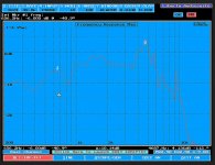
"Mountainside graphs" (or as I like to think of them - the colorful topographic maps) are Cumulative Spectral Decay graphs (CSD) that show the nature of a cone's resonance. Think of a metal bell and whacking it with a mallet - it will ring strongly at it's natural resonance and then slowly decay over time. Maybe it'll ring at some harmonics too. Same with a driver cone but you actually want as little resonance as possible.
Now look at the axes (DA175 graph is below again). As usual, the x-axis is the frequency response and the y-axis is loudness in SPL's. I guess the next axis is the z-axis and shows the amount of time the cone keeps ringing for.
So this graph is telling you how clean it is in the time domain. It gets fed a signal that starts and then stops (like a mallet). Now if the cone was perfect, it would start and stop instantly as well and therefore just be a tall thin wall of dark red (a vertiginous drop-off 😛). Instead, you can see that it keeps ringing for different lengths of time at different frequencies. The colors are there just to help you see the different time periods. So it does it's least ringing between about 10,000 and 30,000Hz, it fades out more or less slowly between 200 and 6,000Hz and it rings kind of badly at around 7,000Hz. There are other reasons that you don't want to use this size driver too high in frequency (too much beaming), so the strength of this driver in terms of a non time smeared signal is going to be below about 3,000 to 4,000Hz.
Cheers
Attachments
So Tony here is a little xmas gift.
My 2nd go at the simulation turned out nicely. I included baffle step loss of 4dB and the baffle diffraction effects of a 9.5" x 34" front baffle with a 1/2" roundover.
Sorry, I should have told you to maybe wait just a bit so you could order all the parts together. Maybe you could contact them and see if they can put these xo parts together with what you just ordered?
Best of luck. More questions are welcomed.
All I can say is WOW! You make it look so easy. Thanks for the gift and I do appreciate your efforts.
Before I do something wrong what happens if the baffle is 10" and the overall box with is 11.5" counting the 3/4" thickness of the sides. I'll make whatever size is needed but thats how I initially planned it.
Not worried about placing another order. No big deal. On the other hand except for the inductors I have most (or maybe all) of those parts.
ODougbo suggested starting a new thread for this project. If I do would you re-post your crossover, graphs and info there?
Thanks again
Tony
Hey, your welcome Tony.
The conventional wisdom says you should not change the baffle width by 2" without also changing the xo. Let's find out if it's true.
Graph 1 below compares the baffle diffraction and loss of the tweeter on both a 9.5" and 11.5" baffle. Essentially you get the same graph but everything is shifted a little down in frequency. Notice however that the baffle step loss of 6dB remains the same in both cases but that the frequency that it starts to drop at changes by about 100Hz.
I've also circled the dip in response that is contributing to the suck out at 5000Hz that you can see in the speaker's PCD summed response that I posted yesterday (3rd graph). The fact that that diffraction dip has now shifted south may actually benefit the overall response. We'll have to see.
The 2nd graph compares the woofer's response on the 2 different baffles. Again, everything is shifted left but the overall loss of 6dB remains the same. Since I'm trying to cross the woofer over to the tweeter at around 2800Hz and the woofer is naturally falling off before that and the diffraction loss has now increased between 1000 and 2000Hz, this one could be problematic. So let's see.
The 4th graph is the summed response using the same xo but this time using the 11.5" baffle diffraction responses. There is definitely a small difference - the 1st one is a little bit flatter but I'm not at all sure whether or not I would be able to hear any difference between the two. Just for fun, dropping the inductor down to 1.3mH and raising the capacitor to 6uF gives us the next graph which might be a little better again although the peaking between about 400 and 1000Hz has also increased just a little bit. Last graph I raised the cap up to 7uF which looks a little better. I'm not sure that you need to but if you wanted to be a perfectionist, that peaking could be easily tamed with a 3 component parallel LCR notch filter in series with the woofer.
So your choice here really but I would probably go with 1.3mH and 7uF and see how that sounds.
Cheers.
Attachments


By all means, start a new build thread if you wish and I'll post in there as well.
Looking at that last graph, I didn't like that the phase wasn't lining up as well any more (that grey dip - the reverse null - isn't as deep) so I fiddled around just a touch more and came up with another, higher parts count flatter version. Let's call it the hi-end version. Graph and schematic are below. It includes the LCR notch filter to flatten that peaking around 700Hz and also tames the rising response that was in the high end with an LR contour filter. Phase tracking is better again. It now models flat with only about plus and minus 1.5dB variation. Not bad.
Again, your choice on what you want to use or try out.
Attachments
Again, your choice on what you want to use or try out.
This is going to take me some time to digest all those graphs and explanations. Although educational for me I did not expect you to do it all over again. I would have just made it 9.5". Does the wider baffle end up being better?
Thanks
It was no problem. Once I've turned the FR and impedance graphs into appropriate computer files (frd and zma files) and then set up PCD, it's really pretty easy to make quick changes and then to fiddle around some more with the xo values. That's one of the benefits of the program.
I would say try to work through what I've posted, although in fact all the changes are very minor and I'm not sure if you (or I for that matter) are going to hear much difference between them. Maybe so maybe not. I don't think you have to stick to the thinner cab, 11.5" will work fine 1 way or another.
In a case like this where you're building something based on a simulation, it's always best to finish the process by listening to the speaker for a bit and then deciding if you think something doesn't quite sound right (eg, too much or too little treble or bass or too shouty) and then adjust a little from there. Maybe just turning a bass or treble knob will make it sing. Maybe it needs a little xo tweek. But this is usually even how the pros finish a design - by using their ears to make any final adjustments.

Even at this stage, you can still go active. The photos I showed are LM3886TF chip amps that provide plenty of power.Wow. I never even heard of active speakers. I assume then it like a sub-woofer with amps built right into the speaker and it just gets fed by the line outs of the amp.
BiAmp (Bi-Amplification - Not Quite Magic, But Close) - Part 1
BiAmp (Bi-Amplification - Not Quite Magic, But Close) - Part 2
Abs
- Status
- Not open for further replies.
- Home
- Loudspeakers
- Multi-Way
- New here with a question