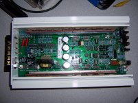
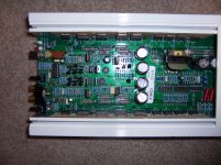
I purchased this as not working and the first thing to do was a visual. It looked like someone tried to repair it and that some of the caps had leaked but those were replaced. On my bench, it would go into protect. While it was doing this I put my scope on the out-puts. Left channel had no dc on it and the right channel had about 25vdc as it would try to start. So I jumped pin 10 to 12 on the 3525 IC and tried again. Confirmed, right channel bad. I checked for shorts on the preamp and final transistors and found everything good . I pulled Q40 and 41 (TIP31 and 32) to half split. This time it powered up with no dc on the right channel. Proved the finals (TIP35 and 36) are good. I probed around on the transistors in the pre-stages and found Q20 and 21(MPSU57 and 07) was in full conduction. I pulled them and they are good. I put in new ones and continued checking. I pulled Q17, 19, 25, 27 (MPSA06 and 56), they were all good, except some of the vias were pulled and traces were lifted
 . I repaired all the vias and traces with a PACE kit and put new A06 and 56's back in. All the resistors checked good and none of the caps were shorted. I cleaned the board to make sure no Cap fluid was causing the problem. During my probing I found the neg side of the +/- 16 volts that feed the op-amp at 25 vdc. Well CR5 and CR23 are the zener's (1n966) and there was a 1n4148 on the neg feed from the power supply. I replaced it with the correct one. It didn't seem to bother the op-amp but I'm replacing it anyway.
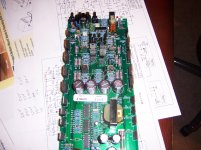
After thinking and looking at the schematic, it hit me to check R85 (zero ohm). Sure enough it was open. I replaced it. While I had this all apart, I pulled the filter caps. Under C35, one of the traces that sends back a protection signal was open, probably from leaking caps. I cleaned it up, repaired the trace and put new caps in. Now to try it again. It works... Idle current good, bias adjustment good, dc offset....Lt channel=0 to 1mvdc, Rt channel=57mvdc. I need to put back the original A06 and A56 trans and try again because it sucks trying to match them.
OK. One question.
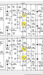
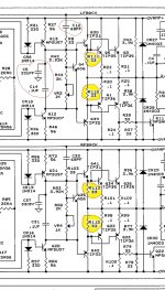
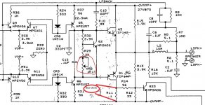
R113 had been changed and a 100ohm carbon film was used. I replaced it with a metal film 1%. All the other R110, R111, R112 looks like they were changed as the soldering job was, well.
Looking at the schematic, these are supposed to be 33ohm.
Anyone know if this was a modification by ZAPCO or were these put in by someone not knowing?
Thanks all😎
. I pulled Q40 and 41 (TIP31 and 32) to half split. This time it powered up with no dc on the right channel. Proved the finals (TIP35 and 36) are good. I probed around on the transistors in the pre-stages and found Q20 and 21(MPSU57 and 07) was in full conduction. I pulled them and they are good. I put in new ones and continued checking. I pulled Q17, 19, 25, 27 (MPSA06 and 56), they were all good, except some of the vias were pulled and traces were lifted. I repaired all the vias and traces with a PACE kit and put new A06 and 56's back in. All the resistors checked good and none of the caps were shorted. I cleaned the board to make sure no Cap fluid was causing the problem. During my probing I found the neg side of the +/- 16 volts that feed the op-amp at 25 vdc. Well CR5 and CR23 are the zener's (1n966) and there was a 1n4148 on the neg feed from the power supply. I replaced it with the correct one. It didn't seem to bother the op-amp but I'm replacing it anyway.After thinking and looking at the schematic, it hit me to check R85 (zero ohm). Sure enough it was open. I replaced it. While I had this all apart, I pulled the filter caps. Under C35, one of the traces that sends back a protection signal was open, probably from leaking caps. I cleaned it up, repaired the trace and put new caps in. Now to try it again. It works... Idle current good, bias adjustment good, dc offset....Lt channel=0 to 1mvdc, Rt channel=57mvdc. I need to put back the original A06 and A56 trans and try again because it sucks trying to match them.
OK. One question.
R113 had been changed and a 100ohm carbon film was used. I replaced it with a metal film 1%. All the other R110, R111, R112 looks like they were changed as the soldering job was, well
. Looking at the schematic, these are supposed to be 33ohm.
Anyone know if this was a modification by ZAPCO or were these put in by someone not knowing?
Thanks all😎
Attachments
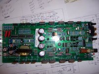
These are the locations that have the 100ohm resistors installed. The schemi shows 33 ohms😕
Attachments
Last edited:
I believe its a revision, I had one or two that had the 100ohm instead of the 33ohm that the schematic showed.
I do see one big mistake (well I would believe it is) the capacitor near the bias pots needs to be a BIPOLAR cap and the one on the board looks like it might have a polarity side on it. Something I would check, it should be a 100uf 25v BP.
Also when I had a few of these I notice the original caps leaked pretty bad and caused a few traces underneath them to OPEN. I had DC voltage on the speaker terminal until I repaired those open traces. Also don't forget to lube the pots and switches.
Last edited:
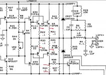
Thanks for the info on the 33ohm stuff... On the caps, The only ones tied to the bias pots are C5, C37, C14 and C31. The only cap I think your talking about is C34. I shows a polarity + on the board and ties to CR15 and CR17, R40 R62 R63. Looks like its part of the DC protect and the schemi does show 2 solid lines, non polarized 100uf. This the one?
Attachments

Yes its the one you circled red on the BOARD (I stated near by the pots, I did not mean connected to the pots, sorry for the confusion). I know it shows polarity on the board silkscreen printing but trust me all the Zapco's I've received for repaired had a BP cap right on that location, I replace it with a Panasonic MUSE BP 100uf 25v.
Check for open traces underneath those larger caps, those where "HF" on certain Zapco models and leaked pretty bad. The damage was done on the rail caps but I would check the filter caps as well.
Check for open traces underneath those larger caps, those where "HF" on certain Zapco models and leaked pretty bad. The damage was done on the rail caps but I would check the filter caps as well.
Ok, kool on the 100uf NP cap... I did mention all the repairs to traces under the large filter caps and all the pulled via's, what a mess.
So would you know why the 100ohm mod was done?
Oh, I did attach the schematic from ZAPCO for anyone that wants it.
Dam, just ordered a bunch of parts from MOUSER a few days ago! Crap!
So would you know why the 100ohm mod was done?
Oh, I did attach the schematic from ZAPCO for anyone that wants it.
Dam, just ordered a bunch of parts from MOUSER a few days ago! Crap!
Last edited:
This is what Zapco told me...
Hi
I would go with the 33 ohm resistors. The amplifier would work with either value, bias adjustment would change, as gain may be affected also.
There are no records showing the change was made to 100 ohm.
Thanks
Mike Boronowsky
ARPA of America
Service Manager
I'm really glad they are communicating and letting schematics go🙂
Yes Mike has helped me with quite a few Zapco's, but am sure the 100ohm is a factory revision, why would I have gotten 4 different Zapcos from 3 different owners (from different parts of the country) and they all had 100ohms resistors instead of the 33ohm the schematics states. Just as he stated both will work, but I left them at 100ohms and had no issues.
That's interesting on the 100ohm.
I did get new parts in and replaced that 100uf NP cap, thanks jeanious2011!
I also put new J109's, A06/56, TL074 and new 16v zeners. Also put new 3300uf caps in it.
Doing this lowered the DC offset to Lt ch. 3mv, Rt ch. 13mv.
Now bias.... I read this and don't think its correct...
According to Zapco
"Turn the bias controls fully counterclockwise. No input & no speakers attached. You need a current meter connected between the main power input lead and the amp, apply power and turn unit on. Take a reading from the current meter - should be around an amp of current. Adjust the left bias control slowly, watch the current meter, add 100ma or .1Amp to the original reading. Then adjust the right channel bias control, add another 100ma or .1Amp to the reading after adjusting left channel.
I can't get that much out of this, maybe he meant 10ma?
I'm using a fluke 87 that will measure down to 1ma. Any suggestions?
Thanks all
Attachments
Last edited:
Found this in an old post from a Z100S2...Ok, I cant remember and I did read most all I can about adjusting bias.
One method is to measure across the emitter resistors.
If I do this, anyone know which ones and how much mvdc is ok on these amps?
I would love to set it correctly.
Thanks all
In the pic I circled the bias adjust and where I think I measure for 1mV.
1moreamp mentioned "Correct spot measure away, I don't see any possible other place to measure it at...
However the Z100C2 has emitter resistors and the Z100S2 does not?
I'll give it a shot and see what happens.
Attachments
That's interesting on the 100ohm.
I did get new parts in and replaced that 100uf NP cap, thanks jeanious2011!
I also put new J109's, A06/56, TL074 and new 16v zeners. Also put new 3300uf caps in it.
Doing this lowered the DC offset to Lt ch. 3mv, Rt ch. 13mv.
Now bias.... I read this and don't think its correct...
According to Zapco
"Turn the bias controls fully counterclockwise. No input & no speakers attached. You need a current meter connected between the main power input lead and the amp, apply power and turn unit on. Take a reading from the current meter - should be around an amp of current. Adjust the left bias control slowly, watch the current meter, add 100ma or .1Amp to the original reading. Then adjust the right channel bias control, add another 100ma or .1Amp to the reading after adjusting left channel.
I can't get that much out of this, maybe he meant 10ma?
I'm using a fluke 87 that will measure down to 1ma. Any suggestions?
Thanks all
When you do as he stated it will also work (I've done it like this also), place a current meter (meaning you might have to set the meter in-line with the B+, according to your meter). Lets say you have exactly 1amp when both bias are fully counterclockwise , then your final reading should be 1.2amps once you adjusted both channels (.1amp/100ma per channel).
I did set it up with the meter in series with the B+. Idle current is 514ma, (,51a).
With both bias fully clockwise, current is 580ma.
I just set it the way Perry shows here... http://www.bcae1.com/temp/ausettingbias.swf
I let it run all day playing dynamic music and it sounds decent.
DC offset is Lt-3/Rt-12 so very good. 😎
Thanks for the info....
With both bias fully clockwise, current is 580ma.
I just set it the way Perry shows here... http://www.bcae1.com/temp/ausettingbias.swf
I let it run all day playing dynamic music and it sounds decent.
DC offset is Lt-3/Rt-12 so very good. 😎
Thanks for the info....
Attachments
- Status
- Not open for further replies.
- Home
- General Interest
- Car Audio
- Zapco Z100C2