Intro: "Blah-Blah"
Even if one does not consider local degeneration and feedback by transistor capacities, almost all amplifiers with negative feedback comprise loops that are nested into each other.
In many cases, the unity loop-gain frequency (ULGF) in the inner of two loops will be much higher than the ULGF in the outer loop. Thus, the stability of the inner loop will not be influenced very much by the outer loop; both can be considered separately. Examples are the Miller compensation loop around the second stage (VAS), the loop due to output stage (OPS) error correction, input-inclusive Miller compensation and so on.
A different case is e.g. transitional Miller compensation (TMC), where the negative feedback around VAS is applied to the OPS up to a certain frequency. The loop around the OPS often will have an ULGF in the order of that in the global feedback loop. In examples in the forum, ULGF of TMC loop is about halve the ULGF of global loop. When investigating stability margins of the loop around the OPS, one usually sees phase margins smaller than that without TMC.
A comparable case is output-inclusive compensation, if the ULGF of the loop around VAS/OPS is set to only a couple of MHz, and that of the global loop to e.g. 1 MHz.
The question is: are the stability margins to be evaluated as critical as in a "standard amp", or do the nested loops obey other rules?
Problem
From the standpoint of linear systems analysis, nested loops always can be transformed into single loops (Mason's rule). This transformation will be done below implicitely by placing the loop gain probe at a point cutting all loops of the circuit: the probe shows the loop gain one would obtain by applying Mason's rule. Therefore, the following examples do not only apply to nested loops, but also to single-loop systems with loop gain showing an equivalent higher-order behaviour.
The question is the same: how to interpret the Bode plots?
After discussions in several threads here, it seems that theory does not provide such simple rules of thumb as for single loops with mainly first-order behaviour below ULGF, e.g. that overshoot only will start below phase margins of lower than 60 degrees.
Example
A problem similar to that with e.g. TMC appears in amplifiers with more gain stages, compensated e.g. by nested Miller compensation. As I'm familiar with that, I will take it as an example.
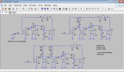
Figure 1: Conceptual circuits.
Figure 1 shows the conceptual circuits of three amplifiers, one with single loop, one with two loops, and one with three loops (all apart from VAS loop).
The top left circuit is the "standard architecture". The VAS is idealised by an integrator built by E1 and C1. It is followed by an OPS with an additional pole whichs relative frequency can be set by parameter P. Changing this pole, one can alter the phase margin of the global feedback loop. G1 is the differential transconductance input stage.
For simplicity, unity closed-loop gain is used. The component values have been set to obtain a nominal ULGF of 1 MHz.
In the top right circuit, an additional nested Miller compensation loop has been added. The resistor R3 ensures that both intermediate loop and global loop may have the same ULGF, but still phase margins of 90 degrees in principle (see next figures). In the bottom circuit, a third loop has been added.
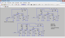
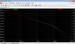
Figure 2: Loop gains of the global feedback loop, OPS pole at 10 MHz.
In Fiure 2, one sees the loop gains of the global loops in all three cases, if the additional OPS pole frequency is high (10 MHz, P=10). If P is set e.g. to 100, the differences between the loop gains almost vanish.
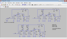
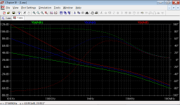
Figure 3: Loop gains around the OPS, with OPS pole at 10 MHz.
Figure 3 depicts the loop gains of the effective loops around the OPS, again with OPS pole frequency of 10 MHz. Nevertheless, the phase margin is reduced to around 55 degrees in the case with three loops. What does this mean?
If one looks at the loop gain slopes at the ULGFs, then one sees that all slopes are almost the same, around 20 dB per decade. The small slope differences again vanish if one increases the OPS pole frequency; the phase margin differences, however, remain.
This seems to indicate that the phase margin at the ULGF is not the only thing to look at. It is a function of the loop gain at all frequencies: a steeper gain slope at frequencies below the ULGF can reduce the phase margin at ULGF to much less than 90 degress, although the gain slope is 20 dB per decade at this point.
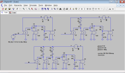
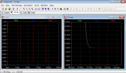
Figure 4: Transient responses with OPS pole of 10 MHz.
Figure 4 confirmes that the reduced phase margin indeed does not lead to any overshoot, as it would be the case for a single-loop system (at least slightly).
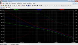
Figure 5: Loop gains around OPS, with OPS pole at 5 MHz (parameter P=5).
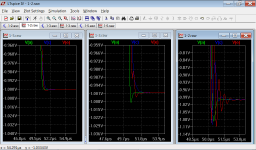
Figure 6: Transient responses for OPS pole at 5 MHz (left), 3 MHz (middle), 2 MHz (right).
Figures 5 and 6 show that even a phase margin of 40 degrees does not lead to overshoots in the 3-loop-circuit. Only with an OPS pole at 3 MHz (phase margin 28 degrees) or 2MHz (phase margin 17 degrees), the 3-loop-circuit starts to ring.
Questions
From these examples, one could conclude the following:
1. Although OPS phase margins are lower with nested loops, the overall circuit starts to produce overshoots at about the same OPS pole frequency as a single-loop circuit.
2. Once overshoot/ringing starts, it is however stronger than in the single-loop circuit.
3. If one starts with a topology with single loop that shows good stability margins for the OPS, one can add additional loops without too much danger, if these additional loops also have good margins on their own (as e.g. in figure 2). The reduction of the OPS phase margin is not very important; it seems that the gain slope at ULGF is more indicative.
The behaviour of the above multi-loop circuits of course can be improved, if one compensates the OPS pole to a certain extend in the additional loops. I intentionally have not done that.
Can anybody comment on these findings? Is there a theory providing arguments which allow to better understand, what's going on?
It would be nice to have a framework in which time and frequency domain analysis lead to comparable results, also for nested feedback or, equivalently, loops with higher-order behaviour below the ULGF.
Best regards,
Matthias
Even if one does not consider local degeneration and feedback by transistor capacities, almost all amplifiers with negative feedback comprise loops that are nested into each other.
In many cases, the unity loop-gain frequency (ULGF) in the inner of two loops will be much higher than the ULGF in the outer loop. Thus, the stability of the inner loop will not be influenced very much by the outer loop; both can be considered separately. Examples are the Miller compensation loop around the second stage (VAS), the loop due to output stage (OPS) error correction, input-inclusive Miller compensation and so on.
A different case is e.g. transitional Miller compensation (TMC), where the negative feedback around VAS is applied to the OPS up to a certain frequency. The loop around the OPS often will have an ULGF in the order of that in the global feedback loop. In examples in the forum, ULGF of TMC loop is about halve the ULGF of global loop. When investigating stability margins of the loop around the OPS, one usually sees phase margins smaller than that without TMC.
A comparable case is output-inclusive compensation, if the ULGF of the loop around VAS/OPS is set to only a couple of MHz, and that of the global loop to e.g. 1 MHz.
The question is: are the stability margins to be evaluated as critical as in a "standard amp", or do the nested loops obey other rules?
Problem
From the standpoint of linear systems analysis, nested loops always can be transformed into single loops (Mason's rule). This transformation will be done below implicitely by placing the loop gain probe at a point cutting all loops of the circuit: the probe shows the loop gain one would obtain by applying Mason's rule. Therefore, the following examples do not only apply to nested loops, but also to single-loop systems with loop gain showing an equivalent higher-order behaviour.
The question is the same: how to interpret the Bode plots?
After discussions in several threads here, it seems that theory does not provide such simple rules of thumb as for single loops with mainly first-order behaviour below ULGF, e.g. that overshoot only will start below phase margins of lower than 60 degrees.
Example
A problem similar to that with e.g. TMC appears in amplifiers with more gain stages, compensated e.g. by nested Miller compensation. As I'm familiar with that, I will take it as an example.

Figure 1: Conceptual circuits.
Figure 1 shows the conceptual circuits of three amplifiers, one with single loop, one with two loops, and one with three loops (all apart from VAS loop).
The top left circuit is the "standard architecture". The VAS is idealised by an integrator built by E1 and C1. It is followed by an OPS with an additional pole whichs relative frequency can be set by parameter P. Changing this pole, one can alter the phase margin of the global feedback loop. G1 is the differential transconductance input stage.
For simplicity, unity closed-loop gain is used. The component values have been set to obtain a nominal ULGF of 1 MHz.
In the top right circuit, an additional nested Miller compensation loop has been added. The resistor R3 ensures that both intermediate loop and global loop may have the same ULGF, but still phase margins of 90 degrees in principle (see next figures). In the bottom circuit, a third loop has been added.


Figure 2: Loop gains of the global feedback loop, OPS pole at 10 MHz.
In Fiure 2, one sees the loop gains of the global loops in all three cases, if the additional OPS pole frequency is high (10 MHz, P=10). If P is set e.g. to 100, the differences between the loop gains almost vanish.


Figure 3: Loop gains around the OPS, with OPS pole at 10 MHz.
Figure 3 depicts the loop gains of the effective loops around the OPS, again with OPS pole frequency of 10 MHz. Nevertheless, the phase margin is reduced to around 55 degrees in the case with three loops. What does this mean?
If one looks at the loop gain slopes at the ULGFs, then one sees that all slopes are almost the same, around 20 dB per decade. The small slope differences again vanish if one increases the OPS pole frequency; the phase margin differences, however, remain.
This seems to indicate that the phase margin at the ULGF is not the only thing to look at. It is a function of the loop gain at all frequencies: a steeper gain slope at frequencies below the ULGF can reduce the phase margin at ULGF to much less than 90 degress, although the gain slope is 20 dB per decade at this point.


Figure 4: Transient responses with OPS pole of 10 MHz.
Figure 4 confirmes that the reduced phase margin indeed does not lead to any overshoot, as it would be the case for a single-loop system (at least slightly).

Figure 5: Loop gains around OPS, with OPS pole at 5 MHz (parameter P=5).

Figure 6: Transient responses for OPS pole at 5 MHz (left), 3 MHz (middle), 2 MHz (right).
Figures 5 and 6 show that even a phase margin of 40 degrees does not lead to overshoots in the 3-loop-circuit. Only with an OPS pole at 3 MHz (phase margin 28 degrees) or 2MHz (phase margin 17 degrees), the 3-loop-circuit starts to ring.
Questions
From these examples, one could conclude the following:
1. Although OPS phase margins are lower with nested loops, the overall circuit starts to produce overshoots at about the same OPS pole frequency as a single-loop circuit.
2. Once overshoot/ringing starts, it is however stronger than in the single-loop circuit.
3. If one starts with a topology with single loop that shows good stability margins for the OPS, one can add additional loops without too much danger, if these additional loops also have good margins on their own (as e.g. in figure 2). The reduction of the OPS phase margin is not very important; it seems that the gain slope at ULGF is more indicative.
The behaviour of the above multi-loop circuits of course can be improved, if one compensates the OPS pole to a certain extend in the additional loops. I intentionally have not done that.
Can anybody comment on these findings? Is there a theory providing arguments which allow to better understand, what's going on?
It would be nice to have a framework in which time and frequency domain analysis lead to comparable results, also for nested feedback or, equivalently, loops with higher-order behaviour below the ULGF.
Best regards,
Matthias
Last edited:
10 feedback fingers
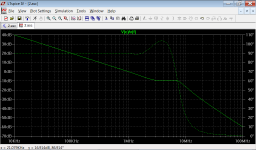
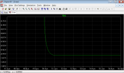
Sorry, but here is still an extreme example with 9 nested loops, so overall 10th-order.
The OPS pole has been set to 10 MHz, OPS phase margin is 19 degrees.
Nevertheless, no ringing can bee seen.
Again, the slope of OPS loop gain magnitude is a bit larger than 20 dB per decade at the ULGF.
Matthias
Loop around OPS:
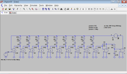
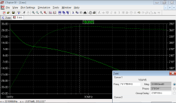
Global feedback loop:
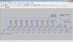
Transient response:
Sorry, but here is still an extreme example with 9 nested loops, so overall 10th-order.
The OPS pole has been set to 10 MHz, OPS phase margin is 19 degrees.
Nevertheless, no ringing can bee seen.
Again, the slope of OPS loop gain magnitude is a bit larger than 20 dB per decade at the ULGF.
Matthias
Loop around OPS:


Global feedback loop:


Transient response:

Last edited:
Can anybody comment...
This is a really excellent post, it has the clarity that results from a perceptive analysis.
Thank you for the work.
It will take time to think about all issues but there was one little point I wonder about.
You use overall loop gain of one. This is a special case, does it make any difference in the results?
Second point should be that the closed loop time domain response is a function of the closed loop frequency response.
Third point, this is Middlebrook sort of stuff, have you checked his website?
So we need to see how that is related to the loop gains that you have posted.
I know it is simple but I would appreciate if you post the ASC.
Best wishes
David
Last edited:
Sorry, but here is still an extreme example with 9 nested loops, so overall 10th-order...
I have written that your circuits are more extreme than is needed.
That may be true as practical amps but they are wonderfully educational!
All the subtle points that are skipped over suddenly become vividly exposed.
The relation between PM and overshoot is usually derived for a second order system, with a small qualification that it varies dependent on the order.
I never paid much attention to the qualification until now, but this makes it very clear.
It is not the nested nature of the loops, it applies also to a one loop system with the same LG function, as you correctly noted.
It is a result of the order of the system.
Now I see why Middlebrook analyses the closed loop response as the sum of two different terms.
Have to reread the work, previous time I lost interest because I didn't see the point.
Best wishes
David
Thank you for the kind words. Some of the ideas only came from the discussions here.This is a really excellent post, it has the clarity that results from a perceptive analysis.
Thank you for the work.
Hopefully, we can find solutions for the questions. If not, it's also not that severe: only analyse higher-order circuits in time domain 😉.
Don't think so. For a larger closed-loop gain, one only had to include a voltage divider into the global loop, and increase the first stage's transconductance by the inverse of its ratio. This will change nothing for the loop gain, and the closed loop gain will just increase by the constant factor.You use overall loop gain of one. This is a special case, does it make any difference in the results?
((EDIT: not so sure anymore. The above is true if one only considers the global loop and sees the rest as a black box inside of the circuit.))
BTW, the two terms "loop gain" and "closed loop gain" seem so similar, although they depict really different things. Are they correct?
This is very true. Sofar, I mostly looked at the loop gain, not at the closed loop response (both in frequency domain).Second point should be that the closed loop time domain response is a function of the closed loop frequency response.
Even more "work".Third point, this is Middlebrook sort of stuff, have you checked his website?
So we need to see how that is related to the loop gains that you have posted.
From KGR Lee's thread in "Pure Cherry", I additionally take the motivation to look at Nyquist diagrams.
So, some things to do and learn.
Kind regards,
Matthias
Last edited:
...
BTW, the two terms "loop gain" and "closed loop gain" seem so similar, although they depict really different things. Are they correct?...
I made the same comment/complaint/beware in my first Linear Audio article.
Easy to confuse. That's one of the reasons I prefer Return Ratio, but not many people are familiar with the term and I am concerned it may just cause different confusion.
I also learned only recently that at least one text book (Ogata) uses the term "closed loop gain" for what I expected everyone called "open loop gain". 😱
On the subject of Middlebrook and related feedback.
Both Ian (Ihan) and I have noticed some Tian loop probes where the phase is the opposite of what we expected.
I plan to use the Middlebrook "Final Solution" to check this out.
But have you ever noticed this? or have any ideas?
Best wishes
David
- Status
- Not open for further replies.
- Home
- Amplifiers
- Solid State
- Phase margins in higher-order / nested loops