I surveyed Internet but I couldn't find satisfactory TECHNICAL or SCIENTIFIC explanation.
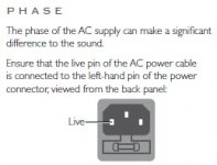
The phase of the AC power supply to some amp DOES make the sound difference. I can clearly detect the difference with my Aleph 0s and I have another amp describing the sound difference according to AC phase as attached picture.
(AC outlet has Hot/Cold and Earth. To find Hot terminal is easy with AC voltage meter.)
Could you advise which URL link or document would help to theoretically understand it?
Attachments
Last edited:
The only scenario I can think of is if your ground is tied to one conductor at the pole or substation, and somewhere else in your local network somebody else has tied the other conductor to ground and this is causing some kind of loop. i.e. there is a fault with your electrical system. But I would think you would have all sorts of weird goings on and tripouts if that was the case.
In a normal system, mains input phase cannot make a difference to the sound.
In a normal system, mains input phase cannot make a difference to the sound.
This has been known for ages. One end of power transformer primary is closer to the grounded core. This obviously leads to asymmetry. There is a very simple procedure, requiring only an AC voltmeter to achieve correct phasing of the primary in order to minimise the AC crud entering the system.
I couldn't believe it before. That's why I started searching the reason.
AC supply to normal user-level usually has Hot and Cold terminal. Hot terminal shows higher AC voltage to Cold. (relative to Earth) At my power environment, Hot is full AC voltage and Cold is almost 0V. That's OK. Hot and Cold can be explained by AC power distribution network.
But what I cannot understand is why the phase of Hot/Cold can make the sound difference. In some explanations, coil winding of toroidal transformer has direction (clock-wise, counterclock-wise) and Hot matches the one of the two-ends. ---> Hmm ... So, what difference is with alternating electromagnetic field? Hardly understand. (Let's call it as Question A)
Moreover, after the transformer, it is rectified and the ripple is suppressed by PSU Cap filters (CLC, CRC whatever). In other words, fully converted and filtered into DC voltage.
So, the possible way to affect the amp is the hypothesis of stronger or less noise power handling with suitable Hot phase into the transformer.
Then, my thought returns Question A: what difference with alternating electromagnetic field?
I didn't think it makes any difference at all since the transistors (and tubes) aren't in need of synchronization with these phase coming in (DC, no phase). Correct me if I am wrong, but it isn't a smart system or is clock synchronized to the maybe 50 - maybe 60 Hz signal. I would hope that the ultra fast diodes would switch all that out at the power boards.
Last edited:
One end of power transformer primary is closer to the grounded core. This obviously leads to asymmetry.
So what. Asymmetry how? For AC crud you need a filter.
It's an old trick from the day of tube amps. Flip the power plug if it buzzes. I have an old Yamaha mixing board that has a 3 position power switch ON-OFF-ON. It flips the plug for you (it's grounded, so no way to flip the plug). Fender guitar amps had this switch too. If the amp was noisy you flipped the switch to reverse the mains polarity. Which mostly just gave you a different noise. 😛
AC leakage current is different depending on whether the innermost winding is at mains N or mains L. A voltmeter sometimes measures dramatically different potentials between primary and secondaries depending on primary polarity.
I somehow thought everyone with an even remote interest in sound quality is using correct phase on the primaries. After all, it costs nothing and takes a minute to get right. And yes, it is often wrong in commercial gear.
I somehow thought everyone with an even remote interest in sound quality is using correct phase on the primaries. After all, it costs nothing and takes a minute to get right. And yes, it is often wrong in commercial gear.
Yeah, this was a laugh for those of us in retail in the 70's because the plugs were 2-wire types and in one orientation, I could "feel" the buzz on the face of a receiver, integrated amp, etc with the back of my hand and in the other, i could not. I won more than a few "bet I can tell you which way the plug is" wagers. It was also promoted by the upscale audio rags to walk thru the system and check each component to get them to agree. We could simply take the volt meter and measure between the chassis of the component and ground to find which orientation would be lowest.
Yes, as they are saying, it's down to different leakage current from the mains transformer getting into the audio circuits.
This is a well known FACT.
Some designers and builders recommend you experiment with the phasing of the mains transformer primary to determine/measure the lowest leakage and adopt that as your preferred final connection.
This is a well known FACT.
Some designers and builders recommend you experiment with the phasing of the mains transformer primary to determine/measure the lowest leakage and adopt that as your preferred final connection.
AC leakage current is different depending on whether the innermost winding is at mains N or mains L. A voltmeter sometimes measures dramatically different potentials between primary and secondaries depending on primary polarity.
I somehow thought everyone with an even remote interest in sound quality is using correct phase on the primaries. After all, it costs nothing and takes a minute to get right. And yes, it is often wrong in commercial gear.
Could you please expand on this?
So how exactly would one test for this with a volt meter? Just plug in the transformer and measure the voltage at the secondaries and find out if reversing the hot and return changes the secondary voltages?
Would a higher voltage be ideal or the lower one?
Could you please expand on this?
So how exactly would one test for this with a volt meter? Just plug in the transformer and measure the voltage at the secondaries and find out if reversing the hot and return changes the secondary voltages?
Would a higher voltage be ideal or the lower one?
Plug only the device under test into the AC power source. Measure the voltage from the shell of an RCA connector to the AC safety ground. Usually the screw on plate of the outlet will do. Flip the AC plug and measure again. Now comes the hard part, plug it in so that the voltage is lowest! 🙂
Do this for each and every piece of gear. This often will clean up the midrange!
Yes there is a good reason for that.
Anything with a rectifier will put even order harmonics decreasing at about 6 db per octave from the rectification frequency. (often double the line frequency.)
Transformer saturation will put odd order harmonics onto the AC line.
The higher the noise frequency the better the coupling to the chassis.
Now go look at a Fletcher - Munson curve and see that hearing sensitivity increases by about 6 db per octave from power line frequencies up to the midrange frequencies.
You can resolve about 100 db differences between tones if you pick the right frequencies!
I have a Namiki DF-100 that I bought in Japan back in the 80s. Basically it measures the potential on the chassis. You connect it to the chassis, punch a button, reverse the plug, punch another button and it tells you which way is best. Same as the reply above but more expensive and it doesn't do anything else unlike a DMM.
Craig
Craig
Plug only the device under test into the AC power source. Measure the voltage from the shell of an RCA connector to the AC safety ground. Usually the screw on plate of the outlet will do. Flip the AC plug and measure again. Now comes the hard part, plug it in so that the voltage is lowest! 🙂
what about when you are building the component? I mean testing which way to wire up the transformer so that it is in the correct phase.
what about when you are building the component? I mean testing which way to wire up the transformer so that it is in the correct phase.
Measure from the frame or use a single secondary lead with all the others open. From my testing it is often a two to one difference or more difference in leakage current.
From my testing it is often a two to one difference or more difference in leakage current.
Do you find that transformer construction and winding geometry make a difference to this? If so, what is preferable?
These are test results. The model numbers are for Signal Transformer parts. Note the toroid has more coupling to the secondary than to the chassis!
Test Points Safety Gnd to Chassis AC Normal/AC Flipped --- Safety Gnd to Center Tap AC Normal/AC Flipped
R Core............19.3/ 3.3.....18.9 /2.7
Toroid.............8.3/ 7.3.......9.6/ 17.1
14A-20-24......1.6/ 0.9........2.0/ 1.2
PC-24-1000.....2.8/ 5.3........3.0/ 1.3
DST-6-24.....,,.1.9/ 1.2........2.4/ 1.4
LP-24-1000.....2.3/ 1.1........2.3/ 1.2
Leakage in uA
- Status
- Not open for further replies.
- Home
- Amplifiers
- Pass Labs
- Question: Why does the phase of AC supply make the sound difference?