How critical is the 18m ohm resistor in the power supply, can it be subsituted with either a 15m/1kv or 20m/5kv ohm resistor feeding the panels?
Also i am having difficulty locating 5kpf capacitors for the ladder circut, i can however find .01/3kv will this suffice?
BTW, Thanks Charlie/Jazzman for updating your website, Your build truley is an inspiration to many of us under taking this project!
Jerry
Yes and yes.
HV module
Hi Folks,
Was inquiring about these modules, look like they could do the job ?!?
Unfortunately don't have my panels yet for trying them out. will be a while for that.😛😛

wonder why those links don't work.😛
Thanks.
Hi Folks,
Was inquiring about these modules, look like they could do the job ?!?
Unfortunately don't have my panels yet for trying them out. will be a while for that.😛😛
wonder why those links don't work.😛
Thanks.
Last edited:
WoW.....That is a nice healthy arc!!!!
They should do just fine!!!
Anything much above 7kv you will have difficulties in trying keep or panels from arcing.
Make sure that you have an adequate stator coating thickness.
Do a mock up test with a the bias supply and a signal from your amp through the step-up transformers at maximum BEFORE you even think about a final assembly, especially if you are using double sided tape.
I was running this range of voltages (10kv) when my little panels fried,
although I didn't build them to go that high.
But, That was only because I was pushing them past their limits, under normal listening conditions (90db) they sounded soooooo good and I had the bias set at 6.8Kv to as much as 8Kv.
I like the sound of them better with a higher Bias voltage.
Besides being more efficient, they seemed to produce a sound that was better damped and had much more authority (increased dynamic range) than it does running a lower bias voltage.
7 Kv is plenty high enough to run without much issues, but can cause issues with the transformer insulation.
Typically 3.5Kv to 5 Kv is what they are rated for and I had a shielded an Antek AS-1206 fail at >4.5Kv using just the audio signal.
Again stay away from the shielded type of transformers.
Your mileage may vary and will have to be found out the hard way. He,he,he,he 😉
If it is variable as the add says then you may want to consider a Regulated variable system using that module.
My circuit is very easy to do and can be found here,
http://www.diyaudio.com/forums/plan...tor-insulation-mylar-coating.html#post2848194
or here,
Does anyone have schematics of a varible HV power supply
Else a LM317 or similar adjustable regulator circuit will suffice.
I used some common BIfet opamp's in that circuit, But I am planning another one using some precision opamp's and digital control next.
That is a very nice price for those modules!!!!
Cheers !!!!
jer 🙂
Last edited:
HV modules.
Thanks Jer,
As you mention I will be trying them with a LM317 regulator.
If these work then they will be the answer to a lot of folks on the same quest hopefully.
Regards,
KBD.
Thanks Jer,
As you mention I will be trying them with a LM317 regulator.
If these work then they will be the answer to a lot of folks on the same quest hopefully.
Regards,
KBD.
My guess is that these Chinese modules are rated at 10 microamps 7kV maximum AC voltage because the HV leads are both yellow in color. You will need a module with DC output if you're planning to use these to charge an ESL diaphragm.Hi Folks,
Was inquiring about these modules, look like they could do the job ?!?
Unfortunately don't have my panels yet for trying them out. will be a while for that.😛😛
View attachment 383435
wonder why those links don't work.😛
Thanks.
Good catch X83,
Was not thinking about the output.😱
I was looking up similar modules and they mentioned it to be DC. I've asked the vendor , lets see. If not a diode in the output will make it a half wave and bring it down to 3KV , what do you say ?
Thanks.🙂
Was not thinking about the output.😱
I was looking up similar modules and they mentioned it to be DC. I've asked the vendor , lets see. If not a diode in the output will make it a half wave and bring it down to 3KV , what do you say ?
Thanks.🙂
I think you would better off purchasing a high voltage multiplier board or a complete kit dedicated for ESL use which will maintain a constant DC charge voltage on the diaphragm.
It makes no difference they are all the same.
A transformer and a diode multiplier stack is all that is required.
It too will be a halfwave output unless you build a full wave type of multiplier circuit.
As long as the input voltage remains constant then the output will remain constant as well, as long as one of the internal capacitors or diode don't go bad.
Using a resistor to feed the diaphragm of 10meg to 30meg will help to protect the supplies internals in case that there is any event of an arc or flash over that would cause an over current situation.
A resistor also helps to keep the supplies voltage stable from being modulated be the step up transformer as well.
This is especially important if you are using the same supply to power both panels.
The CCFL units I had mentioned have an AC output.
It shouldn't take very much current to power the panels unless you have a lot of leakage.
You will know this when you remove the bias voltage and they stop playing quickly.
Mine have been known to stay playing for many hours or even a day or so until the charge finally dissipates from the diaphragm.
jer 🙂
Last edited:
Thanks Jer,
Those modules are AC ouputs. there are also 70-100 KV modules with DCout.
With the CCFL units how did you go about rectifying /controlling the output?
Those Bias circuits you designed are very good too. There are so many possibilities , they all look good.😉😉
Those modules are AC ouputs. there are also 70-100 KV modules with DCout.
With the CCFL units how did you go about rectifying /controlling the output?
Those Bias circuits you designed are very good too. There are so many possibilities , they all look good.😉😉
The specs state that the CCFL's are AC output.
I did a very deep search on them and one day I finally turned up a schematic of them in a catalog from the company that makes them.
They just use a couple of transistors in a multivibrator configuration to drive the transformer.
I don't recall any regulation built in to it either, there may have been a zener diode but I don't remember.
I had found this odd for a constant voltage output type.
Maybe they mis-marked the data in the catalog or something.
Since then, I have lost the URL to the only PDF I have found that showed the schematic.
If I am lucky, Maybe, I will find the PDF again buried deep somewhere in my 100's of 1000's of files. 😉
I haven't used one yet, as I am still waiting on a fellow DIYer that said he had one boxed up for to send to me!!!!
He has been very busy and when it gets here I will be able to work with it and post the results for everyone.
jer 🙂
For those looking for the EMCO F40 and F30 modules , there are a bunch on Eb%y for $30-$40 /pc. Just got two for myself.
Cool !!!
Those look like nice little modules and not a bad price considering what I have seen them go for new when they first came around.
Here is the data sheet,
http://www.emcohighvoltage.com/pdfs/fseries.pdf
The F40 will be good, although personally I would go as high as the F50 or F60 if one can be found.
You will understand once you get your panel running how much 6db extra efficiency is just by doubling the bias supply voltage.
Even though a large panel will run fine and get very loud with 3Kv of bias the extra 6db of efficiency means that the amp won't have to be driven as hard (6db less) in order to reach the same SPL.
I am planning on finishing my little panel very soon ( I know I keep saying this!!!) in order to get some solid measurements on drive requirement per SPL.
To give you an idea I was getting about +90db at one meter( or maybe it was 95db at .5 meter) with my little panel with a 5Vpeak signal into a 1:160 step up ratio and 6.8kv of bias!!
This is about the equivalent of 1 watt reference level voltage wise.
Actually a little more as 1 watt into 8 ohms is 4Vpeak, But it is only used as a reference term when applying it to ESL's.
At half the bias at about 3.5kv the output was at 84db and to get back to the 90db range the amp has to drive twice the voltage and this equates to 4 times the amount of power that the amp has to produce.
Just by doubling the bias voltage it wouldn't have to work as hard and run much cooler.
I was using my little 80watt Awia cd player to do those tests.
When I doubled it to 10-12kv it increased another 6db.
But, I then started having coating breakdown issues and ultimately burned up the panel when I hooked my much Bigger Crown DC300a up to them because I got tired of the Awia shutting down every time I hit some peaks over the 20V to 30v range.
At 20v peaks (with the Awia) I was getting around +105db at .5 to 1 meters on my desktop with a potential to do more.
This is incredibly loud for a little desktop system and I know larger panels can easily exceed this.
My little woofer couldn't keep up past 95db!!!
So then, My research continues on !!!!
Cheers !!!
jer 🙂
Last edited:
Hi,
What is the size of the panel and measurement frequency? Without it SPL values are a bit pointless IMO.
The most energetic music spectrum of music is typically below approx 200Hz so the final max. SPL is mostly determined by sensitivity in this region.
In case of ESL and dynamic hybrid it's often woofer that must handle this range so it could be paired with less sensitive ESL.
That's assuming active filtering of course.
Some comments on BIAS voltage. Too high and problems with membrane stability/corona and reliability arise. If you look at commercial designs most of them target about 2 kV/mm or less. There must be a reason for this. Corona and sparks are not to everyone's taste!
A panel catching fire may spectacular to watch but what if speaker is left unattended ?! 😱 Pointless waste of panel! 😀
Regards,
Lukas.
Hi,
What effect does a high DC offset have on the panel?
Al
Hi, if you are talking about dc offset on amplifier outputs then effect can be large. Dc offset can partially or even copletely saturate step up transformer and cause high levels of distortion. That's assuming there is no series capacitor connected with transformer's primary.
Hi, Yes DC offset from amp outputs. ? If DC gets into the primary, can it be passed on to the secondarys, and if so, create the panels to arc and flash, or create unstability
My panel size (diaphragm) is/was 3.25" X 9.75" with about 5/8" border for the frame.
I was using white and pink noise as well as sine test tones for my measurements.
Yes, I know that those were extreme voltages and it was quite exciting when the panel exploded but very depressing at the same time.
Luckily the are cheap to build!!!
The goal of my little experiment was to prove that there was a 6db increase of the sensitivity for every doubling of the bias voltage.
I was able to run as much as 10kv of bias at normal levels <95db quite well the way the were.
But they were right at the edge of breakdown and I spent more time taking them apart trying to fix the leaks than I spent listening to them or just building a new ones like I already have done here,
A Segmented Stator Desktop ESL
The second goal was to see how high of voltage I could go with the coatings I had used at the time when I made them back in 2003.
Some deterioration had set in through the years and had weakened them a bit.
The did surpass such DC voltage tests of about 15KV or more when I built them.
Although I didn't have any means to accurately measure such voltages at the time, as it was calculated by how many stages that I used in my voltage multiplier and its input voltage.
Also the length of the arcs it produced was a good positive indication as well as to how much voltage was being produced.
I did for about 10 to 15 minutes in 2010 have had about 25Kv to 30Kv p-p across the stator's the First time they blew up.
And I kept trying to fix them to do it again ever since then.
This was after I First fired them up again after they were laying dormant for the last 7 years.
I have explained this several times in other threads.
The whole goal was to find what the limits were, and, How to improve them to get every last bit of efficiency out of them since they are small panels and don't have a lot of surface area to start with.
When I First fired them up, I struggled to get any sound out of them at all and thay were blown away by the 8" sub that I was using at the time.
So, My goal became "What does it take for them to have an equal efficiency with the woofer I was using".
Since they had three times the area and a capability of at least 3 to 4 times the Xmax of my dynamic midranges, they should at least match their performance if not surpass it.
So I kept pushing them until I reached my goal!!
Therefore my measurements are something that can be compared too, and, they do come very close to what the ESL calculator predicts as well, Much to my amazement!!!
Electrostatic Loudspeaker (ESL) Simulator
DeltaStar, DC cannot pass from one winding to another in a transformer, it is strictly an AC device!!!
What does happen is that if there are any DC currents in any of the winding's this increases the residual magnetic flux level that is stored in the core, a Bias Level if you will.
Raising this Bias Level by an increased DC current flow in the winding's causes the saturation level of the core to be effectively lowered.
When a AC voltage ( or current in the winding, as the magnetic flux in the core is proportional to the current flowing in the wire divided by the number of turns as per frequency) is induced, it is added to the biased magnetic flux level caused by the DC offset current, therefore decreases the transformers headroom for core saturation.
The DC current in the winding is calculated by simple Ohms Law of the DC offset voltage divided by the winding's DC resistance.
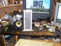
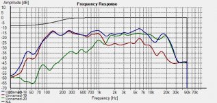
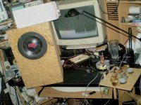
The First Two pictures are of the very last setup when it burned for the last time and the actual calibrated frequency response of the combined and individual drivers.
No particular crossovers were used and it was biamped.
Only the shelving filters on my mixer was used to EQ the setup.
Also I was using both channels of my Awia CD player amp that I used during my transformer study back in 2010.
jer 🙂
I was using white and pink noise as well as sine test tones for my measurements.
Yes, I know that those were extreme voltages and it was quite exciting when the panel exploded but very depressing at the same time.
Luckily the are cheap to build!!!
The goal of my little experiment was to prove that there was a 6db increase of the sensitivity for every doubling of the bias voltage.
I was able to run as much as 10kv of bias at normal levels <95db quite well the way the were.
But they were right at the edge of breakdown and I spent more time taking them apart trying to fix the leaks than I spent listening to them or just building a new ones like I already have done here,
A Segmented Stator Desktop ESL
The second goal was to see how high of voltage I could go with the coatings I had used at the time when I made them back in 2003.
Some deterioration had set in through the years and had weakened them a bit.
The did surpass such DC voltage tests of about 15KV or more when I built them.
Although I didn't have any means to accurately measure such voltages at the time, as it was calculated by how many stages that I used in my voltage multiplier and its input voltage.
Also the length of the arcs it produced was a good positive indication as well as to how much voltage was being produced.
I did for about 10 to 15 minutes in 2010 have had about 25Kv to 30Kv p-p across the stator's the First time they blew up.
And I kept trying to fix them to do it again ever since then.
This was after I First fired them up again after they were laying dormant for the last 7 years.
I have explained this several times in other threads.
The whole goal was to find what the limits were, and, How to improve them to get every last bit of efficiency out of them since they are small panels and don't have a lot of surface area to start with.
When I First fired them up, I struggled to get any sound out of them at all and thay were blown away by the 8" sub that I was using at the time.
So, My goal became "What does it take for them to have an equal efficiency with the woofer I was using".
Since they had three times the area and a capability of at least 3 to 4 times the Xmax of my dynamic midranges, they should at least match their performance if not surpass it.
So I kept pushing them until I reached my goal!!
Therefore my measurements are something that can be compared too, and, they do come very close to what the ESL calculator predicts as well, Much to my amazement!!!
Electrostatic Loudspeaker (ESL) Simulator
DeltaStar, DC cannot pass from one winding to another in a transformer, it is strictly an AC device!!!
What does happen is that if there are any DC currents in any of the winding's this increases the residual magnetic flux level that is stored in the core, a Bias Level if you will.
Raising this Bias Level by an increased DC current flow in the winding's causes the saturation level of the core to be effectively lowered.
When a AC voltage ( or current in the winding, as the magnetic flux in the core is proportional to the current flowing in the wire divided by the number of turns as per frequency) is induced, it is added to the biased magnetic flux level caused by the DC offset current, therefore decreases the transformers headroom for core saturation.
The DC current in the winding is calculated by simple Ohms Law of the DC offset voltage divided by the winding's DC resistance.
The First Two pictures are of the very last setup when it burned for the last time and the actual calibrated frequency response of the combined and individual drivers.
No particular crossovers were used and it was biamped.
Only the shelving filters on my mixer was used to EQ the setup.
Also I was using both channels of my Awia CD player amp that I used during my transformer study back in 2010.
jer 🙂
Attachments

Last edited:
It's not Soylent Green, it's PHOTOSHOP!Hi Folks,
Was inquiring about these modules, look like they could do the job ?!?
Unfortunately don't have my panels yet for trying them out. will be a while for that.😛😛
View attachment 383435
Ben
- Status
- Not open for further replies.
- Home
- Loudspeakers
- Planars & Exotics
- ESL Power supply question?