When transistors are linear why cant one make class A with little bias as much as 200ma per transistor at 40v and use them in parallel like 5 of them?
There's nothing stopping you apart from the fact that it would be a class-ab amp, class-a only up to 8 watts (into 8 ohms).
There will not be any thermal runaway in the case isnt it?
That would depend on how big your heatsink was and how good your bias servo (Vbe multiplier) was.
Hi,
There is essentially no problem designing an output pair for high
optimum aB bias and then using multiple pairs to increase the
nominally Class A region of operation.
There is trade off between low Re's for higher bias and current
sharing in the multiple output devices. I reckon 333mA each
and 3 output pairs is doable for 1A standing current.
rgds, sreten.
(aB = optimum B bias, AB = overbias with gm doubling)
Last edited:
Member
Joined 2009
Paid Member
When transistors are linear
It's a tradeoff because transistors aren't linear.
As I understand, when you drive more current through a transistor their intrinsic Re provides degeneration that tends to result in improved linearity. Higher currents can also affect other parameters such as increased transconductance and increased Ft. Using multiple paralleled power devices also increases the total capacitance that the driver stage has to cope with (not so bad with transistors compared with FETs but still it happens). More devices means more $ along with larger pcb (longer traces), and more holes to drill in your heatsink. However, with more devices you apply less voltage between base-emitters for the same total current into the load - which means you are operating over a smaller part of the I-V curve of the devices and this has a very nice effect of reducing distortion.
Last edited:
32Wpk is the same as 16W32W peak would give you 16W rms, not 22.
It comes from the power formula for sinewave signals:
P=Ipk^2 * Rload / 2
10pair of MJE15034/5 each biased to 180mA (18mVre) gives a total output bias of 1.8A.
That is good for 52W of ClassA output into 8r0.
The stage could go on to supply ~100W into 4r0 in ClassAB and this without the gm doubling that happens with most push-pull ClassA output stages.
That is good for 52W of ClassA output into 8r0.
The stage could go on to supply ~100W into 4r0 in ClassAB and this without the gm doubling that happens with most push-pull ClassA output stages.
Transistors are not linear. They follow an exponential law for transconductance. This means that 5 transistors in parallel behave more or less exactly like one bigger transistor - the same nonlinearity.
Their current gain is approximately linear, but droops at the ends.
There are two ways to get linearity with transistors:
1. carefully balance off different exponential responses - only possible for low gain in small signal circuits with constant temperature - Barry Gilbert was the expert at doing this
2. use lots of negative feedback (including degeneration and followers)
If you don't use either of these techniqies then you are happy with nonlinearity.
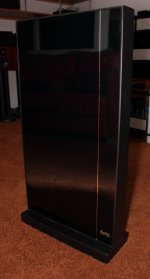
More devices means more $ along with larger pcb (longer traces)
Stereo power amp example from the late '80s, output stages with hundreds of TO92 devices. (height of 4 feet)
Attachments
10pair of MJE15034/5 each biased to 180mA (18mVre) gives a total output bias of 1.8A.
That is good for 52W of ClassA output into 8r0.
The stage could go on to supply ~100W into 4r0 in ClassAB and this without the gm doubling that happens with most push-pull ClassA output stages.
52watts?
P = I^2 x 8ohms = 4 x 8 = 32watts. (I rounded up to 2 amps)
Perhaps there is something here that I am not following...
_-_-bear
if a Push-Pull output Stage is biased to 1A then the maximum ClassA current is 2Apk.
This is covered in my first post.
If 10pr is adopted as in the suggestion of my second post then the output bias for optimum ClassAB is 1.8A and that gives a maximum ClassA output of 3.6Apk
It is because my suggestion is rather different from the 5pr proposal that I posted two separate posts so that confusion did not arise.
You quoted my post and to me it seems that my second post is quite clear that 18mVre and 10 times 180mA gives 52W of ClassA into 8r0.
- Status
- This old topic is closed. If you want to reopen this topic, contact a moderator using the "Report Post" button.
- Home
- Amplifiers
- Solid State
- class A amp with transistors sound better with 200ma bias per trans x 5