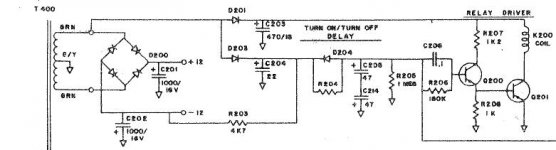
this is the DC detect circuit. both the DC detect and the SOA switch turn on Q205 which is tied to the -12 rail and quickly turns off the relay not only by turning off Q200, but it also dumps the charge on C205 and 214, so that R204 needs to begin charging them again.
Attachments
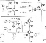
this is the SOA detect circuit. the wire marked PROTECT at the top is what connects to the SOA switch at R209, 210. this circuit is duplicated in both R and L channels. for transistors other than MJ15022,23, the RC time constant needs to be recalculated to find new values for R31,32,33,47,48,49
Attachments
Andrew,AndrewT said:Hi,
l
Now compare a relay passing DC current to a speaker or to a shorted terminal.
As the contacts start to open (equivalent to scratch start) the arc establishes and continues as long as there is sufficient voltage & current to maintain the plasma flow across the gap.
If the contacts have very wide separation, the arc should extinguish before reaching the rated voltage.
That unfortunately is the problem. Narrow separation to give low voltage switching ability and contacts that melt easily when the arc passes.
I suspect that an opening relay does not require much help in establishing the arc with or without inductance in the circuit.
What we really need are big contact gaps and contacts that don't suffer from melting and erosion until the arc has extinguished. I further suspect that these two characteristics are not conducive to good audio.
I like your analogy and it makes sense.
burnedfingers said:Burnedfingers,
In all the commercial amplifiers I have worked on and repaired and all the commercial systems I have worked on I have yet to see a relay with a welded set of contacts.
I'm not going to say that in some strange circumstance it might not happen. You also have to realize that engineers designing the various amplifiers over the years have also pondered the possibility of the same event. Altec Lansing's 9440 power amplifier used a magnet attached to the relay. I have even taken the magnet off the relay and still didn't experience any problems with the relay failing to unlatch.
I assume the magnet helps the relay drop out faster.
With respect to DC ratings I am finding 30VDC ratings on contacts not 24.
I don't see where inductance is relevant. It might be of some small consideration IF the protection circuits didn't act as quickly as they do. Fortunately the modern protection circuits react very quickly minimizing any damage. I have yet to suffer the loss of a driver due to amplifier malfunction with a properly designed and working protection circuit. Forget the fuses and poly switches because they don't work.
At any rate the protection circuits such as the TA7317 seem to function properly so my personal opinion is why are we trying to re-invent the wheel. If something works then use it and if it isn't broken then don't try to fix it.
Have you been able to determine the delay for the relay to drop out?
AndrewT said:Hi,
I've seen a couple of sites state that the diode across the relay coil slows down the relay release time.
I have also seen that reducing the hold in current to near minimum reduces relay response times, i.e. allows it to release more quickly.
There are a couple (or maybe more) threads on this.
I've done some testing and recorded the results. The diode holds in the relay a little longer. A compromise is an r/c network. It speeds up the relay drop out, but also allows some overshoot from the coil. My findings were consistent with Rod Elliott's in his relay project #33.
Mooly said:Way back at the start of this thread I mentioned I was looking into a way to overcome the inherent delay caused by the integrating network of most DC offset detection schemes and ways to speed up the turn off of the relay under fault conditions. I would appreciate comments (bad or good) on the following circuit idea. This is only at present an idea (and only the first part of the circuit-no relay drive and power on delay yet) but initial results are promising, the circuit is exactly as designed, and I know some of the component choices and supply rail values are a bit weird, but I know from experience the folly of making untested changes, even if they seem a good idea on paper at the time. One obvious complaint is the fact that it requires connection to the wiper of the volume control but it is via an extremely high impedance that works into a virtual earth, and I would be looking to "up" the value of the 6.8meg input resistors. The input has to be attenuated by a value equal to the feedback factor of the power amp and is set by R1 and R2 so that the inputs to the two OpAmps are identical, the 47pf cap forms a simple low pass filter, the two outputs then be fed to a comparator (TL072 at the moment) . A + or - 100mv dc offset triggers the output, so a 30 to 1 attenuation at the input would give + - 3 vdc detection of offset.
I would welcome any comments or opinions, if you think it's a non starter please say so.
Edit, Will probably be away till Friday.
Regards Karl
What happens under severe clipping?
you also want the turn-on delay and quick dropout to avoid turn-on and turn-off thumps.
severe clipping should be avoided, but the amp should also clip cleanly if driven that hard. if the amp clips cleanly on both peaks (+/-), then there shouldn't be a whole lot of offset, unless it's a really asymetrical waveform causing it, but that doesn't happen very often in music anyway. besides, even then, a DC servo should correct for it.
severe clipping should be avoided, but the amp should also clip cleanly if driven that hard. if the amp clips cleanly on both peaks (+/-), then there shouldn't be a whole lot of offset, unless it's a really asymetrical waveform causing it, but that doesn't happen very often in music anyway. besides, even then, a DC servo should correct for it.
d3imlay asks,
Unclejed mentions,
Regards Karl
This has not yet been tested under clipping, but I would certainly expect the output to mute instantly as the input and outputs differ (Which I would say is a good thing really). When clipping occurs however briefly, this is really the same as saying there is a D.C. voltage at the output terminals equal to the rail voltages. The fact that there is no R/C time constant involved ensures very fast triggering. This was tested with a square wave input to simulate a fault, with the "base line" of the input signal offset to zero volts (tested same for negative going input as well). On a dual timebase 'scope and comparing the rising edge (or falling) of the input signal and the output to the test LED, there is no (only a few 10,s of microseconds) delay in triggering. These milliseconds saved ( and when you have an R/C time constant that allows for full output at 20hz, this is significant ) is where I believe the damage to speakers can occur.What happens under severe clipping?
Unclejed mentions,
I couldn't agree more. Doug Self discussed this several years back and came up with a very simple circuit whereby a transistor that is triggered by each mains half cycle keeps resetting a "timer" . This would detect not just a very quick on/off sequence but even if there was a mains drop out of a few cycles. On triggering the full "power up sequence" i.e. switch on delay was initiated.you also want the turn-on delay and quick dropout to avoid turn-on and turn-off thumps.
Regards Karl
Hi,
does any one have experience with the number of times, in a day or a year, that the mains could omit a single half cycle?
If we were to use a missing pulse counter to trigger release of the speaker relay, how often would the music cut out?
does any one have experience with the number of times, in a day or a year, that the mains could omit a single half cycle?
If we were to use a missing pulse counter to trigger release of the speaker relay, how often would the music cut out?
Hi Andrew, We are very lucky in the U.K. our mains is generally excellent. The timer I refer to is nothing more than a C/R network, the whole thing being constructed from 3 or 4 transistors and a few resistors. It's as simple as any circuit posted here and allows for an instant disconnect at power off, followed by a full power on delay at switch on (Even with a rapid on/off cycle). It's foolproof and in 4 years of daily use of 2 hours (or sometimes much more) use has never tripped falsely. A single missing cycle won't trip it but 3 or 4 in a row will and changing a single component value would provide greater tolerance if it was a problem in other parts of the world. I suspect the fact that it disconnects so quickly also helps to stop any "noise" caused by any arcing of the mains switch as it breaks contact. Switch off is totally silent, even if you operate the mains switch very slowly.
Hi Mooly,
instant off and delayed on is OK and I have it on some of my amps and pre-amps.
But, I'm thinking about the missing pulse detector for near instant off. I do suffer brown outs and loss of power and power cuts. This PC is always powered by my UPS. My Stereo isn't.
The missing pulse detector is easy and based on a 555 timer costs a few pence.
Hi again Andrew, what effect do you get when your supply has a "wobbly", an amp with it's large value caps could run on for some time, particularly a class B. Does this cause a problem with your source components such as C.D. players etc locking up or shutting down. If you don't detect the loss of A.C. I can't see how you can get an instant disconnect. Again I suppose a lot depends on the amp and how it behaves at power up/down. My amp uses a D.C. servo so the settling time is very long, about 4 seconds before you can connect a speaker silently so this foolproof "startup" sequence is of particular concern to me. (or more correctly my speakers 😉 )
Cheers Karl
Cheers Karl
AndrewT said:Hi,
does any one have experience with the number of times, in a day or a year, that the mains could omit a single half cycle?
If we were to use a missing pulse counter to trigger release of the speaker relay, how often would the music cut out?
I don't think a missing pulse detector provides any real advantage. If power does go off and back on it will take several cycles. Look at it this way. The lights are actually flickering 60 (or 50) times per second, but the persistence of our vision doesn't notice it. So if you even see a flicker in the lights, the outage lasted for a few cycles. The transistor with R/C time constant is more than adequate to detect a loss of power.
Hi,d3imlay said:I don't think a missing pulse detector provides any real advantage.
If one requires fast detection of loss of power then missing pulse does offer a big advantage.
The standard short duration RC tends to work as you have described, detection and triggering within a few half cycles. But, what if one REQUIRES triggering that is faster?
Self's 2mS and missing pulse set to somewhere in the range 1 to 5mS both should be able to achieve muting within 5 to 10mS of power loss.
i've seen missing pulse detectors used in large industrial safety-of-life applications (starting a generator to power high volume water pumps for fire protection systems), but an amplifier isn't "mission critical". a simple power loss dropout would suffice. you could always put the amp on a UPS if you think it's worth it. it would keep the amp running during short brown-outs. a 1000w UPS can be had cheap if you know a computer tech, and a dead one you might get for free. 90% of dead UPSs are caused by sulfated batteries. replace the batteries and you're in business. i worked for a company that replaced their gel cell batteries with motorcycle batteries in the in-house UPSs. not only were the batteries cheaper, but with proper maintenance much more reliable. you can't maintain gel cells, so when they start showing signs of going bad, there's nothing you can do.
unclejed613 said:
you could always put the amp on a UPS if you think it's worth it. it would keep the amp running during short brown-outs. a 1000w UPS can be had cheap if you know a computer tech, and a dead one you might get for free. 90% of dead UPSs are caused by sulfated batteries. replace the batteries and you're in business. i worked for a company that replaced their gel cell batteries with motorcycle batteries in the in-house UPSs. not only were the batteries cheaper, but with proper maintenance much more reliable. you can't maintain gel cells, so when they start showing signs of going bad, there's nothing you can do.
I strongly disagree with using batteries for applications they weren't intended. Sulfation of cells is due to undercharging, which is not a common failure mode of UPS batteries.
If voltage regulation is the only requirement, a ferroresonant transformer is ideal and requires very little maintenance.
I would apreciate some insight into a problem I´m having.
I´m using relays to switch between music and home theater configurations using the same speakers ( front left and right sit next to each other with a crosstalk barrier, when switched to home theater both reproduce the center channel information).
When the relay is on (theater) there will be no sound coming from the speakers until I crank up the volume, then sound will resume with no problems thereafter.
Since the other channels (also going through relays) do not show this issue I guess it has something to do with the fact that two speakers instead of one are taking the load?
BTW, The problem also happenned when I used manual heavy-duty switches instead of relays.
Do you mean you are using relays to connect the speakers to different amplifiers? Just make sure the outputs of different amplifiers/channels are never connected together to the same speaker.
That you need to turn up volume before it works sounds like you need switches with another contact material, higher pressure or contacts that rub against each other a bit (knife switches would be nice 😉) - many switches/relays won't make a reliable connection at low currents because the contacts need to spark a little to clean them.
That you need to turn up volume before it works sounds like you need switches with another contact material, higher pressure or contacts that rub against each other a bit (knife switches would be nice 😉) - many switches/relays won't make a reliable connection at low currents because the contacts need to spark a little to clean them.
Thanks for your response. I am switching both neg. and pos. so there are never two amps on the same speaker. The relay I am using is the one rated 8A on the link below.
If cranking up the volume does not overload the amp I can live with it; the relays are expensive and I am using 8, (it´s a biamped active system)www.findernet.com/comuni/pdf/S40EN.pdf
If cranking up the volume does not overload the amp I can live with it; the relays are expensive and I am using 8, (it´s a biamped active system)www.findernet.com/comuni/pdf/S40EN.pdf
DC offset relay protection - arcing
Hi – I’m new to DIYaudio
This thread is quite old, and if not still active I will post elsewhere.
I ‘m currently building a power amp and intend to use output relay protection. I would like to invite comment on the following.
There is a problem when using output relay to break DC offset fault, with heavy DC voltage and current present in this situation. See references below for more detail on this:
Speaker DC protection with relays
& Bob Cordell’s amplifier book pg 338
When the relay contacts break on fault detection, an arc often forms between open contacts, thus continuing high DC voltage to speakers, and probable destruction. Fuses may not blow as the current is still flowing through the speaker impedance.
Halfgaar’s solution is to use SPDT relay with the NC contact grounded. This should ensure the arc is sent to ground rather than to speaker. However this seems rather brutal (potentially shorting rail to ground) and could increase the chances of arcing, arcing severity, fuses regularly blowing even with normal operation, and possible damage to amplifier components including the relay (if not already destroyed) ?
Bob Cordell’s book fig 15.19 shows the NC contact grounded via 8R resistor, this I believe is to ground the flyback voltage from the speaker, rather than grounding the arc away from speaker (it is too high a value for this). I don’t fully understand the need for the 1st set of flyback diodes and zobel network between amp and relay as, a) the zobel is required in the presence of inductive load and cable to prevent UHF oscillation (see D.Self book), and this is not present when the relay is open, and b) the 2nd set of flyback diodes should channel speaker flyback voltage to rail, regardless of whether relay is open or closed?
I intend to implement a compromise, using a resistor to ground from NC relay terminal, but lower value, calculated in the following way, in order to either blow fuses quickly, or ensure DC voltage seen across speaker is reduced.
Using 3R resistor connected to NC relay contact, to ground, and assuming 8R 100W speaker:
Max current, ignoring rail sag = 42V / (0.22R + 3R//8R) = 17.5A
Typical 3A fast blow break time @ 17.5A = 20ms
(use fuse with decent specified DC breaking capacity, e.g. 0225003.MXP, and 1 fuse per channel).
If the relay arc is not ‘perfect’ then lower current may be seen, however the voltage across the speaker terminals will be lower prorata.
E.g. @ 8.75A, fuse blow time av 100ms, voltage sustained across speaker for that period 19V. Assuming 100W speakers this should be survivable.
I believe the above will also work for 4R speakers, with increased fault currents and reduced fuse blow lags. There also seems to be enough headroom for increased fuse rating or possibly even using slow or medium type fuse. Although fuse break times vary, given the high currents involved they should always break quickly, whether 20ms or 50ms ?
Offset detector lag for a full 42V DC offset is 40ms in my circuit.
Any comments most welcome. Intended circuit below.
https://dl.dropboxusercontent.com/u/11137726/relay-arcing.gif
This thread is quite old, and if not still active I will post elsewhere.
No thread is ever totally dead! We can resurrect it! 🙂🙂🙂
I ‘m currently building a power amp and intend to use output relay protection. I would like to invite comment on the following.
I'm also doing design right now and pondering on the same things.
There is a problem when using output relay to break DC offset fault, with heavy DC voltage and current present in this situation. See references below for more detail on this:
Speaker DC protection with relays
I was just considering changing my current design to do as suggested with double throw switches tied to ground. That would be a better configuration.
Halfgaar’s solution is to use SPDT relay with the NC contact grounded. This should ensure the arc is sent to ground rather than to speaker. However this seems rather brutal (potentially shorting rail to ground) and could increase the chances of arcing, arcing severity, fuses regularly blowing even with normal operation, and possible damage to amplifier components including the relay (if not already destroyed) ?
That's not how I saw it. The switches are turned around with their common going to the speaker and not to the amp's output. So when the relay releases, it's the speaker that is connected to ground and not the amp's output. At least that's how I understand it, and it makes sense to me, as the inductance in the speaker can cause the arc to remain longer and shorting it to ground can only stop this quicker.
I don't think the spreakers are in danger that way and the amp gets an open output and is no longer hooked to the speakers.
Bob Cordell’s book fig 15.19 shows the NC contact grounded via 8R resistor, this I believe is to ground the flyback voltage from the speaker, rather than grounding the arc away from speaker (it is too high a value for this).
There is only so much energy stored in that speaker's inductance, it will stop more quickly that way than if still arcing from the amp's output I think.
But there is one possible use for that extra resistor to ground in that place, it's to sense a short on the speaker line, so that can be used by the protection circuit to decide if it's closing that relay or not, so at least on power-up the shorted speaker line can be detected before the amp sees it, and it will never see it if this is handled properly.
I've been thinking about such a detection too...
zobel network between amp and relay as, a) the zobel is required in the presence of inductive load and cable to prevent UHF oscillation (see D.Self book)
There is one good reason to have that zobel wired right at the amp's output and before a protection relay. When the output relay has opened, the only load the amp can see is that zobel. Better that than no load...😀
One thing I would do: move the flyback diodes to the other side of the relay, where they belong, on the amp's output and leave the speaker on its relay common alone.
I've seen both, the zobel on either side of the output R//L. I wonder what's the best position. Many people say leave it off the main pcb and put it on the output terminals on the case. But then it's far away from the amp, most likely way after any eventual protection relay and if the amp gets unhooked (by the relay), then it has no load left. Perhaps it doesn't hurt to have more than one zobel. Or I've even see amps (crown) with only a cap on the output, not a zobel.😕😕😕
- Status
- Not open for further replies.
- Home
- Amplifiers
- Solid State
- Loudspeaker Relays