Having two I2S sources, namely Amanero asynchronous USB-to-I2S and S/PDIF transceiver WM8805, and a dual differential WM8471 DAC.
Regarding the SCK, SD and WS lines swichting can be as simple as this:
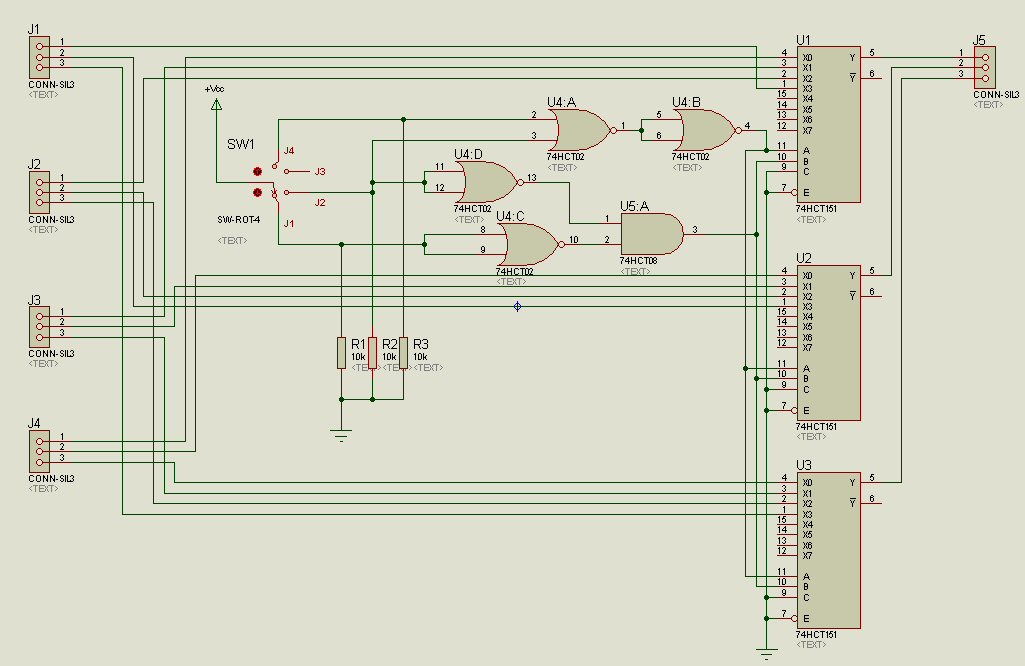
But what to do with the MCK (clock) lines? The Amanero has a 24.576 MHz clock, the WM8805 derives it's frequencies from a 12.00 MHz clock. Do I have to switch both the MCK lines as well? If so, will a MUX suffice?
Shed some light on me please ...
Regarding the SCK, SD and WS lines swichting can be as simple as this:
But what to do with the MCK (clock) lines? The Amanero has a 24.576 MHz clock, the WM8805 derives it's frequencies from a 12.00 MHz clock. Do I have to switch both the MCK lines as well? If so, will a MUX suffice?
Shed some light on me please ...
Last edited:
WM8805 has: "Configurable clock distribution with selectable output MCLK rate of 512fs, 256fs, 128fs and 64fs."... so it's MCLK output should definitely not be 12MHz. Do you gave a schematics or at least description of your WM8805 transceiver?
Check out OTTO-II 2:1 Digital Switch Module from TPA
Use it's 0.1" (2.5mm) pin headers not the terminal blocks.
Zsolt
Check out OTTO-II 2:1 Digital Switch Module from TPA
Use it's 0.1" (2.5mm) pin headers not the terminal blocks.
Zsolt
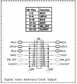
Zsolt, thank you for your answer. Regards the 12.00 MHz clock on the WM8805 have a look at this excerpt of the WM8805 evaluation board schematic:

Seems like the 8805 derives any needed frequency from that 12.00 MHz clock ...
What IC is used on the OTTO II?
Seems like the 8805 derives any needed frequency from that 12.00 MHz clock ...
What IC is used on the OTTO II?
The diagram you shown is for external clock input. I just ran through WM8805 datasheet but I think it uses this input (10-27MHz) to generate through its internal PLL a correct MCLK - so don't think you should care much about it.
What you should care is the Digital audio interface figure from eval board datasheet: see attached - you have there all I2S signals + MCLK
Don't know what Otto II actually uses - email the designer. Some sort of Quad 2-Input Multiplexer, e.g. 74VHC157 or similar.
Zsolt
What you should care is the Digital audio interface figure from eval board datasheet: see attached - you have there all I2S signals + MCLK
Don't know what Otto II actually uses - email the designer. Some sort of Quad 2-Input Multiplexer, e.g. 74VHC157 or similar.
Zsolt
Attachments
The WM8805 uses 10-27 MHz clock in software mode only, if I understood the datasheet right. In hardware mode the clock must be 12 Mhz.
I'm beginning to think about a possible alternative to the WM8805 ...
I don't feel comfortable with the idea to have the MCK line running through a mutliplexer - propagation delay may (will?) add jitter.
Again, thank you!
I'm beginning to think about a possible alternative to the WM8805 ...
I don't feel comfortable with the idea to have the MCK line running through a mutliplexer - propagation delay may (will?) add jitter.
Again, thank you!
This clock's frequency has nothing to do with output MCLK frequency. Forget about this 12MHz clock. MCLK frequency is generated through WM8805's internal PLL to be relative to the input stream frequency.The WM8805 uses 10-27 MHz clock in software mode only, if I understood the datasheet right. In hardware mode the clock must be 12 Mhz.
If you are using it in hardware mode - WM8805 pg30:
"FREQMODE control is fully automatic to ensure that the MCLK output is maintained at 256fs relative
to the S/PDIF received sample rate.
In hardware mode, the OSCCLK must be 12MHz and hence the external crystal (or applied XIN clock) must be 12MHz. No other OSCCLK frequencies are supported in hardware mode"
Don't have to. Simply use H8 output - you have there all I2S lines (incl. MCLK) - and forget about the 12MHz clock.I'm beginning to think about a possible alternative to the WM8805 ...
No, propagation delay is not same with jitter. Somewhere on the forum were discussing (was also a table) about jitter added by different flip-flops... don't remember exact numbers but it was irrelevant (<1ps if I remember well). Ask Otto II designer, he might know - also he might recommend you a good multiplexer (maybe VHC or AHC series)I don't feel comfortable with the idea to have the MCK line running through a mutliplexer - propagation delay may (will?) add jitter.
You could also use impedance matched RF relays, but you must design a proper PCB for it otherwise is meaningless.
Zsolt
Thank you even more, Zsolt!
Slowly, very slowly I'm getting an idea ...
So I understand: When SPDIF input sample rate is 44.1 kHz, then MCLK output is 11.2896 MHz, 96 kHz in is 24.576 MHZ out and so on up to 192 kHz/49.152 MHz.
So the 12.00 MHz clock on the WM8805 is not a master clock in common sense as it works in indivisible relation to the sample rate of the SPDIF input.
It seems I'm somehow mixing up different things and/or I lack the basic understanding of the master clock concept in general ... 🙄
Anyway: In what I want to achieve I neither can use the Amanero's 24.576 MHz nor the WM8805's 12.00 MHz clock as a master clock:


I conclude that I need an ASRC. Or is there any voltage-out DAC that takes any sample rate without an ARSC?
Slowly, very slowly I'm getting an idea ...
MCLK output is maintained at 256fs relative to the S/PDIF received sample rate.
So I understand: When SPDIF input sample rate is 44.1 kHz, then MCLK output is 11.2896 MHz, 96 kHz in is 24.576 MHZ out and so on up to 192 kHz/49.152 MHz.
So the 12.00 MHz clock on the WM8805 is not a master clock in common sense as it works in indivisible relation to the sample rate of the SPDIF input.
It seems I'm somehow mixing up different things and/or I lack the basic understanding of the master clock concept in general ... 🙄
Anyway: In what I want to achieve I neither can use the Amanero's 24.576 MHz nor the WM8805's 12.00 MHz clock as a master clock:
I conclude that I need an ASRC. Or is there any voltage-out DAC that takes any sample rate without an ARSC?
Last edited:
The 12MHz is the master (in a way) as it is used by the PLL to generate the desired MCLK.So I understand: When SPDIF input sample rate is 44.1 kHz, then MCLK output is 11.2896 MHz, 96 kHz in is 24.576 MHZ out and so on up to 192 kHz/49.152 MHz.
So the 12.00 MHz clock on the WM8805 is not a master clock in common sense as it works in indivisible relation to the sample rate of the SPDIF input.
Check the PLL in datasheet if you want to know more how MCLK is generated.
Anyway: In what I want to achieve I neither can use the Amanero's 24.576 MHz nor the WM8805's 12.00 MHz clock as a master clock:
Amanero has "fixed" MCLK of 22.5792MHz/24.576MHz so according to the sample rates image WM8741 should work from 44.1Khz to 192KHz fine.
WM8805 seems to have fixed MCLK (fsx256) in hardware mode so it will work from 44.1KHz to 96KHz. For 176.4/192KHz you need (probably) software mode to have MCLK fsx128.
I think I cannot help more. Connect both to your DAC and see how it works. Use an Otto II or similar to switch between I2S sources.
Zsolt
Zsolt, you've helped me a lot, I could not ask for more.
Meanwhile I've found a appropriate MUX: SN74CB3Q3257
Now I have to learn how I get such a doo-hickey working. Switching it with a pushbutton (momentary switch) an having a LED signalling
the chosen input lines would be great ...
Meanwhile I've found a appropriate MUX: SN74CB3Q3257
Now I have to learn how I get such a doo-hickey working. Switching it with a pushbutton (momentary switch) an having a LED signalling
the chosen input lines would be great ...
Hi,
Similar question on my part. I have a waveIO (latest version) and a CDpro2 drive that I would like to switch into a DIY TDA1541 dac as I2s signal. All parts available.
Can I just use a simple 4-pole switch?
Similar question on my part. I have a waveIO (latest version) and a CDpro2 drive that I would like to switch into a DIY TDA1541 dac as I2s signal. All parts available.
Can I just use a simple 4-pole switch?
- Status
- Not open for further replies.
- Home
- Source & Line
- Digital Line Level
- Connecting two I2S sources to one DAC - How to switch, what to do with the MCK lines?