grounding scheme for dac
This is a question for anyone: Should there be ground between chassis and the psu or dac boards? Thanks all. Looking forward to starting my build. -freeman
This is a question for anyone: Should there be ground between chassis and the psu or dac boards? Thanks all. Looking forward to starting my build. -freeman
still waiting here on the east coast also, should i be concerned? 😀
I think we should be more concern since we are in California and live close to Subbu.😛
Could someone please send me the bom, or just tell me what type of transformer to get, what are the needed specs. I didn't get the bom since I registered for the gb later than everybody else and I could check if my local shop has the right kind of transformer. The other parts i'll get from the parts gb 🙂
Subbu responded to a message from me, he explained he sent them out in batches. He mentioned in an earlier post he has been busy with work traveling. I can relate.
Bill
Bill
I see on the schematic Q1,Q2 and Q3 (Q2 and Q3 seems paralleled). I believe this is an error and there is no Q3.
What is the secret of soldering Q2 as the case covers entire soldering pads and there is no acces with soldering iron ?
What is the secret of soldering Q2 as the case covers entire soldering pads and there is no acces with soldering iron ?
I see on the schematic Q1,Q2 and Q3 (Q2 and Q3 seems paralleled). I believe this is an error and there is no Q3.
What is the secret of soldering Q2 as the case covers entire soldering pads and there is no acces with soldering iron ?
they are difficult but do-able, at the very sides of the Q2 package you should see exposed contacts that run under the xo.
tin the pads and align the xo over them with flux and apply heat to one exposed contact by pressing the flat of the bit firmly against the side for a second or so. Check it has taken and the alignment and continue with the rest. Careful with overheating.
You can check continuity by C17 and L3 pads to the very side of the xo contacts - only two of the xo contact pads are used, is this correct?
Hope that's clear 🙂
Last edited:
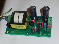
Managed to finish first DAC. Soldered carefully, washed the pcb after finished soldering smd parts but sound is bad.
It sounds like a poor tuned FM station, my stomach tells me that is something related with spdif interface. Any idea, what to check ?
It sounds like a poor tuned FM station, my stomach tells me that is something related with spdif interface. Any idea, what to check ?
An externally hosted image should be here but it was not working when we last tested it.
An externally hosted image should be here but it was not working when we last tested it.
An externally hosted image should be here but it was not working when we last tested it.
Some new findings: when spdif is not locked is complete silence, after spdif loks to source and sound coming also that strange pink noise appears also.
Spdif looks like it takes longer that experienced with other dacs to lock to source.
Spdif looks like it takes longer that experienced with other dacs to lock to source.
"dry joints" on the WM8804 ? Looks like that on the picture, at least the left pin connected to the crystal. Or a overheated WM8804 ?
Did you measure both 3.3 V regs ? BTW use either thinner wires for the connections or use Molex KK.
Did you measure both 3.3 V regs ? BTW use either thinner wires for the connections or use Molex KK.
Last edited:
All voltages are ok before and after installing L3,4,5,6
I have reflowed the Wm8804 pins as i had suspected the same dry joints.
As i have 3 dac kits so assemble i will start building a new one to see if i will experience same issues with this one.
I have reflowed the Wm8804 pins as i had suspected the same dry joints.
As i have 3 dac kits so assemble i will start building a new one to see if i will experience same issues with this one.
Did anyone hear any news about the status of the parts group buy recently ? I've got my boards, but so far no parts.
PJN
PJN
Second try was succesfull, working from first PLAY.
I really like what i hear now in the first minutes of listening.
First words coming into my head now is musicality and ease of playing music.
Start soldering guys ! 🙂
I really like what i hear now in the first minutes of listening.
First words coming into my head now is musicality and ease of playing music.
Start soldering guys ! 🙂
Status of the PCB's and Parts?
What is the status of the PCB's and parts group buy. I have received nothing, and
it's been months since I paid for these items and services. Any news, status?😕
What is the status of the PCB's and parts group buy. I have received nothing, and
it's been months since I paid for these items and services. Any news, status?😕
Parts GB has yet to ship. I believe Phil (Korben69) is waiting on a shipment that is due November 12. I received my boards a few days ago...
Second try was succesfull, working from first PLAY.
I really like what i hear now in the first minutes of listening.
First words coming into my head now is musicality and ease of playing music.
Start soldering guys ! 🙂
Thanks that is what we like to hear from the buyers.
- Status
- Not open for further replies.
- Home
- Group Buys
- "Subbu DAC V3 - ES9023/WM8804 SPDIF & Power Supply PCB" Group Buy