The auto router did a better job because your component
placement was better.
There is quite a bit of room for improvement, though.
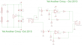
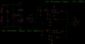
Think about how the signals move through the amp.
Here is a simplified explanation:
Power flows from the batteries, through the op amp,
out through the headphones and back, returning through
the rail splitter and finally back to the batteries.
We want to make this path as short as practical.
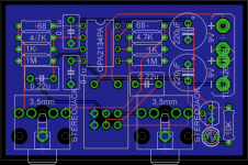
I think the power supply should be on the left side of the
board, behind the output jack.
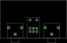
Try and keep your ground plane on the bottom as
unbroken as possible. If it has to be broken up, keep
the area around the power supply and output jack
intact.
See what you can come up with given that knowledge.
Don't feel bad if you have to rip up and redo the board
many times. I usually go through half a dozen tries before
I settle on one I like. then I sit on it for a week and look
at it again. It usually gets changed a little then as well.
Designing a board is very much like art, but with rules.
placement was better.
There is quite a bit of room for improvement, though.
Think about how the signals move through the amp.
Here is a simplified explanation:
Power flows from the batteries, through the op amp,
out through the headphones and back, returning through
the rail splitter and finally back to the batteries.
We want to make this path as short as practical.
I think the power supply should be on the left side of the
board, behind the output jack.
Try and keep your ground plane on the bottom as
unbroken as possible. If it has to be broken up, keep
the area around the power supply and output jack
intact.
See what you can come up with given that knowledge.
Don't feel bad if you have to rip up and redo the board
many times. I usually go through half a dozen tries before
I settle on one I like. then I sit on it for a week and look
at it again. It usually gets changed a little then as well.
Designing a board is very much like art, but with rules.
The auto router did a better job because your component
placement was better.
There is quite a bit of room for improvement, though.
Think about how the signals move through the amp.
Here is a simplified explanation:
Power flows from the batteries, through the op amp,
out through the headphones and back, returning through
the rail splitter and finally back to the batteries.
We want to make this path as short as practical.
I think the power supply should be on the left side of the
board, behind the output jack.
Try and keep your ground plane on the bottom as
unbroken as possible. If it has to be broken up, keep
the area around the power supply and output jack
intact.
See what you can come up with given that knowledge.
Don't feel bad if you have to rip up and redo the board
many times. I usually go through half a dozen tries before
I settle on one I like. then I sit on it for a week and look
at it again. It usually gets changed a little then as well.
Designing a board is very much like art, but with rules.
Avro, thank you for the generous support and advice.
I will follow the recommendations and re-layout the PCB.
Last edited:
Still with the auto router though.
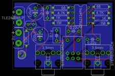
Move the 0.1u caps to either end of the op amp.
They should be as close to the power pins on the op amp as possible.
The two input caps can go side by side right behind the input jack.
You can delete the two 68 ohm resistors...they are not needed.
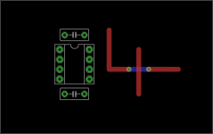
Try and keep all of the traces on the top layer as much as possible.
You can use Vias to under a trace if you need to cross it.
Like this:
Move the 0.1u caps to either end of the op amp.
They should be as close to the power pins on the op amp as possible.
The two input caps can go side by side right behind the input jack.
You can delete the two 68 ohm resistors...they are not needed.
Try and keep all of the traces on the top layer as much as possible.
You can use Vias to under a trace if you need to cross it.
Like this:
Attachments
Avro, thank you for the patience and advice.
I will play with the ideas you have given.
You are right.
When I compared the last few Autoroute boards with the one I routed manually.
I used less wire when routing manually.
I think that I need to do the PCB layout in a more systematic way.
I am studying some PCB layout tips and guides on the Internet.
I found that I made many mistakes in the last few layouts.
I will write down a list of PCB layout rules and standardize the dimensions of the components
before I proceed to re-layout the PCB again.
i might be a little late,
just wondering but why are you using two 9 volt batteries when you are using a tle2426 for virtual ground?
is the sonic difference between one and two 9 volt batteries really that big when you are not using real ground on the two 9 volt battery configuration?
why not just a single 9 volt to save space, cost and copper since you are "mass producing" the cmoys especially given how expensive 9 volts are becoming lately?
Last edited:
i might be a little late,
just wondering but why are you using two 9 volt batteries when you are using a tle2426 for virtual ground?
is the sonic difference between one and two 9 volt batteries really that big when you are not using real ground on the two 9 volt battery configuration?
why not just a single 9 volt to save space, cost and copper since you are "mass producing" the cmoys especially given how expensive 9 volts are becoming lately?
Thank you for the comments.
Personally, I have never used any Cmoy.
But I have seen some versions of Cmoy using only one 9V.
Although I am aware that there are some opamps work as low as +/- 2.5V.
But I am not sure whether a single 9V battery can drive the amp well, esp. with low output voltage source. On the other hand, a 2 x 9V version allows opamp rolling.
For the past few days, I am struggling about whether to be a minimalist or be a greedy guy. Here are some of my struggles.
1. to make the PCB smaller by removing the decoupling/bypass film caps near the opamp
2. replace the expensive Alps switch volume pot
3. remove the quieting 68ohm resistor ?
Yes, there are always some trade-off.
I have not finalize my work.
Any kind of advice or comments are welcomed.
1. to make the PCB smaller by removing the decoupling/bypass film caps near the opamp
No.
If you are using 2X9V batteries then no rail splitter is required & don't omit bypass caps.Secondly you can use 2X4 AA or AAA cells (in battery holders) to generate +/-6V for CMOY(If space permits). Pls stick to JRC4556AD DIP8 only as these can drive h/p in the region of 16 Ohms.
If you are using 2X9V batteries then no rail splitter is required & don't omit bypass caps.Secondly you can use 2X4 AA or AAA cells (in battery holders) to generate +/-6V for CMOY(If space permits). Pls stick to JRC4556AD DIP8 only as these can drive h/p in the region of 16 Ohms.
yeah thats my point with the tle2426, but without protection circuitry, i really think one shouldnt use real ground since difference in voltage between the two 9 volts could potentially kill the amp and the headphones. tangent has a great article about grounds
i agree with marce on the caps as well, if your source (audio player or computer or whatever) has a tiny bit of dc offset and you didnt have input caps, then the dc offset would also be amplified by your op amp's gain stage and the amplified dc offset might damage headphones as well
PS: you could always use imgur to upload images
- Status
- This old topic is closed. If you want to reopen this topic, contact a moderator using the "Report Post" button.
- Home
- Amplifiers
- Headphone Systems
- Yet Another Cmoy - PCB layout with Eagle and making PCB