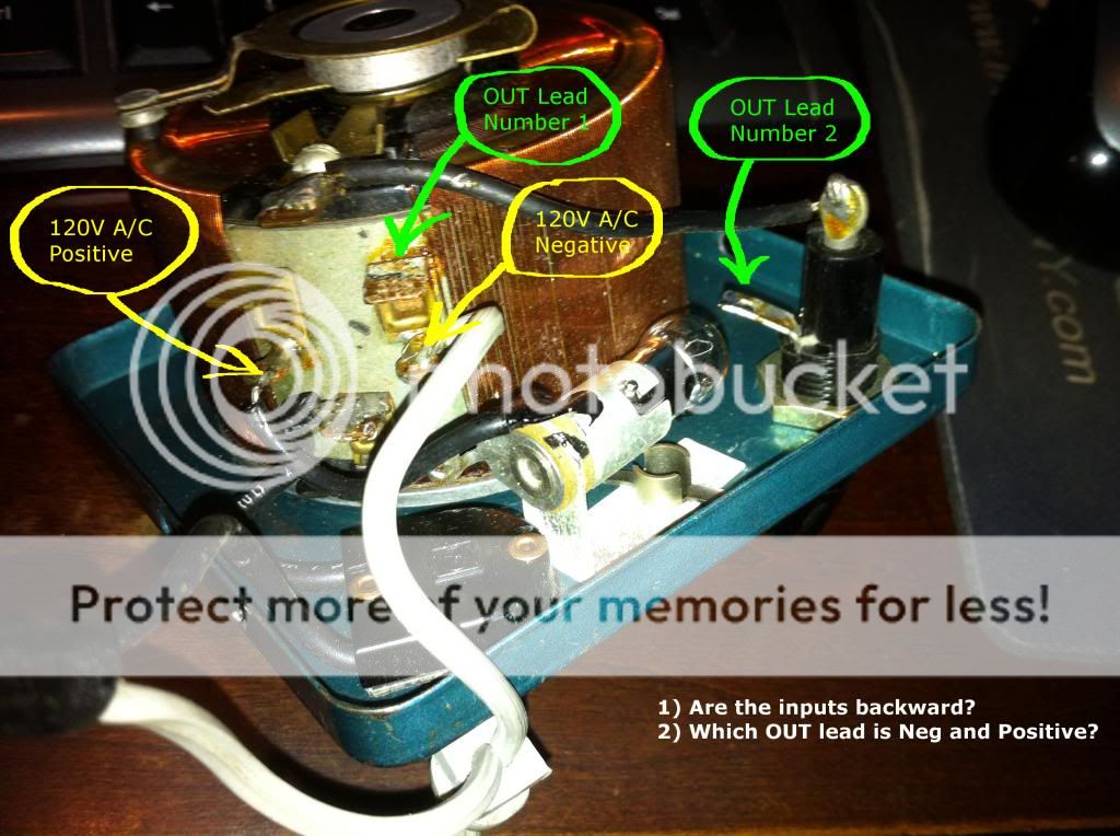
I have some questions as to whether this variac is wired into the 120v plug correctly and which output should be negative or positive. Take a look:
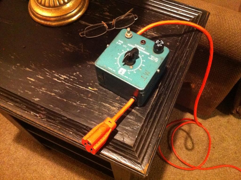
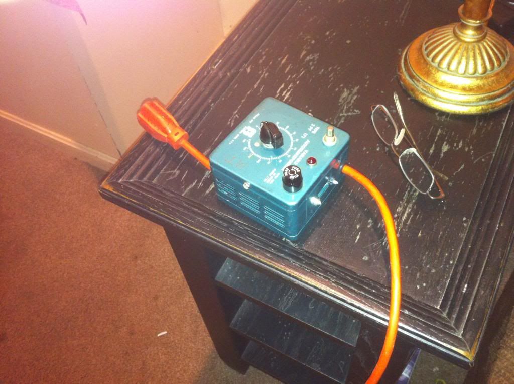
Here is a picture of the top of the 1.75A variac:

And another picture of the meat:

Here is a picture of the top of the 1.75A variac:
And another picture of the meat:
The correct terminology for AC voltage in this case is hot & neutral, not positive and negative. The neutral on a standard US receptacle is the wider blade.
The wiring looks correct. The hot (black) lead goes through the power switch, then the rheostat, out of the rheostat through the fuse, and then to the output. The neutral is common.
Have you verified the the rheostat is in good working order?
I would change the power cord to include a ground, and then tie that to the case for safety.
Correction edit: I suppose if you intend to use this for DC, then the black wire will be positive, and the white is negative.
Last edited:
The correct terminology for AC voltage in this case is hot & neutral, not positive and negative. The neutral on a standard US receptacle is the wider blade.
The wiring looks correct. The hot (black) lead goes through the power switch, then the rheostat, out of the rheostat through the fuse, and then to the output. The neutral is common.
Have you verified the the rheostat is in good working order?
I would change the power cord to include a ground, and then tie that to the case for safety.
Thank you. No I have not tested anything yet. The fuse holder was broken when it arrived, so that needs fixed first. I will pick up a new 2WG cord and a ground lug while I'm at Radio Shack getting a fuse holder. The Ebay seller tested everything before he shipped it, but I was being cautious before I did anything, hence the post here.
As for connecting the output cord, the fuse (OUT Lead 2) gets the hot, the lug on the rheostat (OUT lead 1) gets the neutral, and the ground goes to the chassis lug. Sound right?
What size fuse would you recommend? The output is 1.75 AMP constant current, 2.2 AMP constant impedance.
Thank you. No I have not tested anything yet. The fuse holder was broken when it arrived, so that needs fixed first. I will pick up a new 2WG cord and a ground lug while I'm at Radio Shack getting a fuse holder. The Ebay seller tested everything before he shipped it, but I was being cautious before I did anything, hence the post here.
As for connecting the output cord, the fuse (OUT Lead 2) gets the hot, the lug on the rheostat (OUT lead 1) gets the neutral, and the ground goes to the chassis lug. Sound right?
That should be correct. The neutral (white) terminal mounted to the side of the rheostat assembly looks to be just a common terminal tie point, correct?
I might just be being picky but I don't like calling this a rheostat. A rheostat will limit current while an auto-transformer (or variac) limits voltage.
And to scott17, I don't think a variac can be used on DC as a rheostat considering a variac's operation is dependant upon the magnetic field that is set up on the toroidial windings from the AC.
Although it is hard to see some things it does look like it is wired correctly, however make sure you are capable of safely working with these things and do not hold me responsible for anything.
What size fuse would you recommend? The output is 1.75 AMP constant current, 2.2 AMP constant impedance.
A 2.5A slo blo fuse should be OK.
Hot and neutral are always applied to the ends of the winding. The load gets attached to the movable brush tap and neutral. Variacs get destroyed when people manage to apply power to the movable brush tap (center) and short the thing out. Remember that this provides no isolation from the line, only the ability to vary the AC voltage.
Some Variacs (actually the trade name for the one made by the General Radio Corp.) will have taps a few windings in from the ends. These can be used so a low line voltage can be corrected up a bit. Typical is 120 VAC input and 0-130 VAC output.
I can't quite tell what's going on in the photo. What's that bottom center connection tied to?
Last edited:
That should be correct. The neutral (white) terminal mounted to the side of the rheostat assembly looks to be just a common terminal tie point, correct?
You are correct, the zip cord's neutral is connected to a double spade, and the zip cord's hot is connected to the switch.
I might just be being picky but I don't like calling this a rheostat. A rheostat will limit current while an auto-transformer (or variac) limits voltage.
And to scott17, I don't think a variac can be used on DC as a rheostat considering a variac's operation is dependant upon the magnetic field that is set up on the toroidial windings from the AC.
Although it is hard to see some things it does look like it is wired correctly, however make sure you are capable of safely working with these things and do not hold me responsible for anything.
Wrong terminology used. I have read that some "can" be used for DC, but in this case I will agree with you and say no.
I might just be being picky but I don't like calling this a rheostat. A rheostat will limit current while an auto-transformer (or variac) limits voltage.
And to scott17, I don't think a variac can be used on DC as a rheostat considering a variac's operation is dependant upon the magnetic field that is set up on the toroidial windings from the AC.
Although it is hard to see some things it does look like it is wired correctly, however make sure you are capable of safely working with these things and do not hold me responsible for anything.
OK, so this is not a rheostat, it's an auto transformer. I actually knew that but didn't feel confident splitting hairs. I promise to practice safety as listed in the pinned safety thread and to not blame anybody for anything. I understand there is no isolation with this device. Point of note, isolation does not make things safe as I recall from all the safety threads I have read. Good practices and being careful and taking time are the best ways to reduce shock. That's why I pick your brains! 🙂
Nice. Glad it worked out. Hopefully you got a great deal on it.
$45 total. Don't know if it's a great deal, but for Ebay it was.
- Status
- Not open for further replies.
- Home
- Amplifiers
- Tubes / Valves
- Wiring variac