
shows the driver's energy storage vs frequency (afaik). If a metal coned driver has a cone-breakup resonance at a certain frequency then a long "tail" will be shown, indicating the driver is ringing at that frequency.
It's really hard to explain just talking in general terms. But you can be sure that if you are using a non-cyclic signal through the driver and determine distortion levels from that, better CSD will have better distortion figures. This may not be true if you do distortion testing with sine waves. Different parts of the CSD has different effects.
In addition to comments by others, I would like to note that a CSD is not the most useful form of measurement because there is absolutely nothing in there that isn't shown in the frequency response curve.
Honestly, I'm not even sure why I post them myself. I think maybe it's because I'm impressed by pretty colors. 🙂 But otherwise, it's just another way of looking at a response curve. Both are generated from the same impulse.
Honestly, I'm not even sure why I post them myself. I think maybe it's because I'm impressed by pretty colors. 🙂 But otherwise, it's just another way of looking at a response curve. Both are generated from the same impulse.
An externally hosted image should be here but it was not working when we last tested it.
I wonder which driver this CSD if for. It looks good for a super tweeter. If the starting marker can be moved to where the phase curve shows minimum phase, the CSD would be more clear. The focus of this driver may not be very good. I think you probably have this plot set at 8~10 samples per line? The 7K~8K region is where you will hear some sort of sonic signature unique to the driver, probably one specific note will stand out during listening if you XO lowere than 10K.
I find them quite important. The ringing causes the note to sustain, so the total power over time is quite high, higher than the peak alone would indicate. In addition, the note continues as the music "moves on", often increasing the audibility, as it is unmasked, or at least masked less well, than it was when it was originally stimulated by an instrument with fundamentals and harmonics. To try to be a little clearer; if the ringing is initiated by a second harmonic of an instrument's note, the fundamental, and fourth harmonic will be sounding at the same time. The ringing then will continue for some period of time (2,3, 5? ) ms after the note is cut off, and then the ringing will not be covered up to any degree by the fundamental and other harmonics. As a result, the audibility is quite high, and I've found in the case of woofer breakup (which tends to fall into the spectral area where the ear is most sensitive anyway) that it is necessary to suppress a ringing peak by 35 to 40 dB to be inaudible, which may well require a trap.
Different charts let you look at the sound different ways just like a good doctor does trying to diagnos a problem. Even looking at the same chart, different doctors may come up with different conclusions. One is familar enough with the basic physics of the driver, one can play with the driver and see what changes result in audible results, and relate it with measured data.
I find them quite important. The ringing causes the note to sustain, so the total power over time is quite high, higher than the peak alone would indicate. In addition, the note continues as the music "moves on", often increasing the audibility, as it is unmasked, or at least masked less well, than it was when it was originally stimulated by an instrument with fundamentals and harmonics ....
Hi ! i would like to say that i agree completely
It is very important. The ringing in the worst cases adds to later impulses.
What i am trying to understand is how much of this ringing can be due to the presence of a passive crossover.
When i measure a spectral decay of conventional speaker there is usually an inductor in series with the woofer ?
Does this inductor affects the spectral decay ?
If yes this is bad.
I have been told that spectral decay and Qts are also linked.
Maybe it is for this that i much prefer the sound of low Qts woofer like Scanspeak (some have Qts= 0.2 😱)
In the ideal transducer the ringing is null, and also rise time is infinite.
The more ideal the better no ? 😉
When i read reviews of very good loudspeakers usually then i discover that they also exceptional driver 😱
Thanks and regards,
gino
Last edited:
First, a properly designed crossover will not ring. A first order crossover, (one L and one C for a two-way) cannot ring, so a simple inductor in series with the woofer is quite safe.🙂
This opens up a whole sub-discipline, filter design. A book like Dickason's "Loudspeaker Design Cookbook" would help a lot. An active crossover is no more or less likely to ring than a passive design with the same response.
Yes, the shape of the response curve is an indicator of ringing; actually the curve in frequency and the ringing in time are two sides of the same coin.
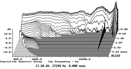
Ringing like that in your remarkable example is caused by mechanical factors as the cone "breaks up" above its useful range. Theoretically, a sharp notch filter could remove that, although it requires a very high-Q filter, very precisely tuned to the exact frequency, and the exact frequency is apt to change from speaker to speaker, or with time or perhaps temperature. More to the point, for that speaker, I'd roll it off at around 3 or 4 kHz. The peak of that ringing should be at least 40dB below flat response, and probably more. The crossover's rolloff may or may not reduce the peak below audibility; at first guess, I'd add a notch filter as well, to be sure the ringing was well below audibility.
Modern crossover emulation software is necessary to design flat response crossovers that take the drivers' responses into account. Back when I was doing this, I used LEAP, which is expensive and excellent. I don't know if it is still available, or what the alternatives are these days. You do need a good background in general principles to use the software properly. MLSSA is a great tool, although finding and maintaining a PC it can run on is becoming a problem.
PS. Looking at the graph again, I notice that the vertical scale is pretty short. It should extend down to -36 at least; I think you'd see much more activity above 5 kHz.
This opens up a whole sub-discipline, filter design. A book like Dickason's "Loudspeaker Design Cookbook" would help a lot. An active crossover is no more or less likely to ring than a passive design with the same response.
Yes, the shape of the response curve is an indicator of ringing; actually the curve in frequency and the ringing in time are two sides of the same coin.
Ringing like that in your remarkable example is caused by mechanical factors as the cone "breaks up" above its useful range. Theoretically, a sharp notch filter could remove that, although it requires a very high-Q filter, very precisely tuned to the exact frequency, and the exact frequency is apt to change from speaker to speaker, or with time or perhaps temperature. More to the point, for that speaker, I'd roll it off at around 3 or 4 kHz. The peak of that ringing should be at least 40dB below flat response, and probably more. The crossover's rolloff may or may not reduce the peak below audibility; at first guess, I'd add a notch filter as well, to be sure the ringing was well below audibility.
Modern crossover emulation software is necessary to design flat response crossovers that take the drivers' responses into account. Back when I was doing this, I used LEAP, which is expensive and excellent. I don't know if it is still available, or what the alternatives are these days. You do need a good background in general principles to use the software properly. MLSSA is a great tool, although finding and maintaining a PC it can run on is becoming a problem.
PS. Looking at the graph again, I notice that the vertical scale is pretty short. It should extend down to -36 at least; I think you'd see much more activity above 5 kHz.
Last edited:
CSD "analysis" or actually graphics can be made to look different very easily, like any such. Ginetto's example looks like it's from Stereophile website. Even they aren't consistent.
I use REW and it is easy to set time window, rise time, smoothing etc. parameters and naturally also scale in xyz. Very small changes make csd grahps look different. All programs have preset parameter but there is no standard. Parameters should be told, without that info they don't give much.
I use REW and it is easy to set time window, rise time, smoothing etc. parameters and naturally also scale in xyz. Very small changes make csd grahps look different. All programs have preset parameter but there is no standard. Parameters should be told, without that info they don't give much.
True, but the rate at which the lines drop should be the same. Other settings effect the smoothness of the curves and the time step between the curves.
First, a properly designed crossover will not ring. A first order crossover, (one L and one C for a two-way) cannot ring, so a simple inductor in series with the woofer is quite safe.🙂
Hello ! so you say that an inductor in series with a woofer does not influence the woofer's response to an impulse ? This is very interesting
I was thinking really in another way. Good to know.
This opens up a whole sub-discipline, filter design.
A book like Dickason's "Loudspeaker Design Cookbook" would help a lot.
An active crossover is no more or less likely to ring than a passive design with the same response.
Again thank you. I did not know this.
Because someone told me that a normal active crossover is able to pass even a square wave without big degradation
Good to know again.
Yes, the shape of the response curve is an indicator of ringing; actually the curve in frequency and the ringing in time are two sides of the same coin.
Ringing like that in your remarkable example is caused by mechanical factors as the cone "breaks up" above its useful range.
Theoretically, a sharp notch filter could remove that, although it requires a very high-Q filter, very precisely tuned to the exact frequency, and the exact frequency is apt to change from speaker to speaker, or with time or perhaps temperature. More to the point, for that speaker, I'd roll it off at around 3 or 4 kHz. The peak of that ringing should be at least 40dB below flat response, and probably more. The crossover's rolloff may or may not reduce the peak below audibility; at first guess, I'd add a notch filter as well, to be sure the ringing was well below audibility.
Modern crossover emulation software is necessary to design flat response crossovers that take the drivers' responses into account. Back when I was doing this, I used LEAP, which is expensive and excellent. I don't know if it is still available, or what the alternatives are these days. You do need a good background in general principles to use the software properly.
MLSSA is a great tool, although finding and maintaining a PC it can run on is becoming a problem.
PS. Looking at the graph again, I notice that the vertical scale is pretty short. It should extend down to -36 at least; I think you'd see much more activity above 5 kHz
Thank you so much for all these valuable information and advices.
Just one last question ... what is your opinion on digital crossovers ?
Some years ago i was just playing with a cheap low end active analog crossover. 😱
A quite well know designer in a forum told to start playing with digital crossover because they are superior. 😕
You can get sharp filters, delay ... maybe even some form of equalization 😱
Is that the way ? 🙄
Thanks a lot and kind regards,
gino
CSD "analysis" or actually graphics can be made to look different very easily, like any such. Ginetto's example looks like it's from Stereophile website. Even they aren't consistent.
I use REW and it is easy to set time window, rise time, smoothing etc. parameters and naturally also scale in xyz. Very small changes make csd grahps look different. All programs have preset parameter but there is no standard. Parameters should be told, without that info they don't give much.
Hi ! yes i took it from that site 😱
Let me please trivialize a little the issue
Music is a series of impulses. So the response to an impulse is very important.
There is an ideal behavior and real behaviors
The more a real driver is close to the ideal the better ... or not ?
The nice thing is that this test should not be very difficult to execute
The bad thing is that is very uncommon
My feeling is that a driver with a great response to an impulse also sounds very very good ... because music is an impulse, in the end.
Thanks and kind regards,
gino
Hi and sorry to answer to my own post 😱
Just to say that i have come to a conclusion.
That the Cumulative Spectral Decay is extremely telling. 😀
The cleaner the plot the cleaner the sound. It cannot be otherwise.
Unfortunately it is not very common in the drivers data sheet like it should.
Also the cabinet and the closed or bass reflex arrangement influence the result.
While many tweeter are from good to excellent the suspects for me are the woofers, higher mass implies longer decay/tail.
I would love to see this test available in the drivers data sheet. 😉
The dynamic behaviour of a woofer is very important.
And i wonder if the CSD performance is linked in some way to the driver Qts ... i have only the feeling that the lower the Qts the better the CSD performance. 🙄
I stop here but before i would like to thank you all for the always kind and valuable advice.
Kind regards, gino 🙂
P.S. i do not understand why the test looks limited to mid-high frequencies by the way like here (i.e. from 400 Hz up)
http://cdn.stereophile.com/images/archivesart/1107DC1fig9.jpg
so i guess my feeling was very wrong ... is not telling anything of valuable about the woofer behaviour 🙁
Just to say that i have come to a conclusion.
That the Cumulative Spectral Decay is extremely telling. 😀
The cleaner the plot the cleaner the sound. It cannot be otherwise.
Unfortunately it is not very common in the drivers data sheet like it should.
Also the cabinet and the closed or bass reflex arrangement influence the result.
While many tweeter are from good to excellent the suspects for me are the woofers, higher mass implies longer decay/tail.
I would love to see this test available in the drivers data sheet. 😉
The dynamic behaviour of a woofer is very important.
And i wonder if the CSD performance is linked in some way to the driver Qts ... i have only the feeling that the lower the Qts the better the CSD performance. 🙄
I stop here but before i would like to thank you all for the always kind and valuable advice.
Kind regards, gino 🙂
P.S. i do not understand why the test looks limited to mid-high frequencies by the way like here (i.e. from 400 Hz up)
http://cdn.stereophile.com/images/archivesart/1107DC1fig9.jpg
An externally hosted image should be here but it was not working when we last tested it.
so i guess my feeling was very wrong ... is not telling anything of valuable about the woofer behaviour 🙁
Last edited:
Go buy (and read) the two mentioned books. You really miss the basics.
Ralf
Hi Ralf !
i tried but too much math ...
What i would like to understand is only if the CSD test is telling something or not.
To understand the all theory is very beyond my reach.
I am surprised that the graph starts only from 400 Hz up by the way. Why ?
Maybe the CSD tells nothing on the bass response ?
Bye, gino
The lower frequencies contain room response.Hi and sorry to answer to my own post 😱
Just to say that i have come to a conclusion.
That the Cumulative Spectral Decay is extremely telling. 😀
The cleaner the plot the cleaner the sound. It cannot be otherwise.
Unfortunately it is not very common in the drivers data sheet like it should.
Also the cabinet and the closed or bass reflex arrangement influence the result.
While many tweeter are from good to excellent the suspects for me are the woofers, higher mass implies longer decay/tail.
I would love to see this test available in the drivers data sheet. 😉
The dynamic behaviour of a woofer is very important.
And i wonder if the CSD performance is linked in some way to the driver Qts ... i have only the feeling that the lower the Qts the better the CSD performance. 🙄
I stop here but before i would like to thank you all for the always kind and valuable advice.
Kind regards, gino 🙂
P.S. i do not understand why the test looks limited to mid-high frequencies by the way like here (i.e. from 400 Hz up)
http://cdn.stereophile.com/images/archivesart/1107DC1fig9.jpg

so i guess my feeling was very wrong ... is not telling anything of valuable about the woofer behaviour 🙁
... and becaue of the finite length in the dime domain of the maesurement window does also restrict the time and freuqency range that can be plotted at the lower end.
If you do the meansurements in an environment that is anechoic down to veeeery low frequencies you can chose a long measurement windo and then you will have your low end extension of the CSD plot.
Regards
Charles
If you do the meansurements in an environment that is anechoic down to veeeery low frequencies you can chose a long measurement windo and then you will have your low end extension of the CSD plot.
Regards
Charles
- Status
- Not open for further replies.
- Home
- Loudspeakers
- Multi-Way
- Cumulative Spectrum Decay. What...?