From the the idea of Belaji, what do you think of this, with only 8 tranies, a simple symetrical Jfet input and no miller or such:
Attachments
Last edited:
From the the idea of Belaji, what do you think of this, with only 8 tranies, a simple symetrical Jfet input and no miller or such:
😎🙂
Can you easily scale it up in power and keep performance? ...say 200-250W/8 level?
What results do you get when you replace R9 and R10 with one resistor and connect that one resistor to the junction of R1 and R2 -- with the ground at that junction removed and replaced by resistor to ground? can you SIM and compare?
-RNM
What results do you get when you replace R9 and R10 with one resistor and connect that one resistor to the junction of R1 and R2 -- with the ground at that junction removed and replaced by resistor to ground? can you SIM and compare?
-RNM
Last edited:
Hi, Richard,
More voltage, I believe yes, those series of Jfets are high voltage (up to 200V). The ones used are 50V.
Same perf ? We will see 🙂
(i am not such a VSSA sectarian, i would prefer one path than 2 ;-)
It looks quite promising, hey ? Fast and Healthy in sim. Amazed by the HF behavior, so clean.
More voltage, I believe yes, those series of Jfets are high voltage (up to 200V). The ones used are 50V.
Same perf ? We will see 🙂
You can imagine it was my first schematic ;-) No good.What results do you get when you replace R9 and R10 with one resistor and connect that one resistor to the junction of R1 and R2 -- with the ground at that junction removed and replaced by resistor to ground? can you SIM and compare?
(i am not such a VSSA sectarian, i would prefer one path than 2 ;-)
It looks quite promising, hey ? Fast and Healthy in sim. Amazed by the HF behavior, so clean.
Last edited:
According to my notions amplifier must be done without general negative feedback. The voltage amplifier (VAS - driver) can be performed by any scheme with any form of NFB current or voltage, or without NFB. In the amplifier without a common NFB it is a little irrelevant. The output stage has to have a negative impedance. Only in this case, you can get the most realistic sound. [FONT=Arial, sans-serif]http://www.rowen.ch/en/poweramp.php[/FONT]
best regards
Petr
[FONT=Arial, sans-serif] [/FONT]
best regards
Petr
[FONT=Arial, sans-serif] [/FONT]
Last, little square signal (50KHz)
Bias: input:5.6mA, VAS 38mA, OPS 160mA
I don't believe-it. Please, don't tell me there is a mistake somewhere !
Bias: input:5.6mA, VAS 38mA, OPS 160mA
I don't believe-it. Please, don't tell me there is a mistake somewhere !
Attachments

Last edited:
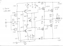
The schematic (need some more work for offset of course)
And even a lot of work...
Boggles my mind that simulations that appear as unrealistic
are propping up the CFA agenda using flawed datas that are
misleading the general public.
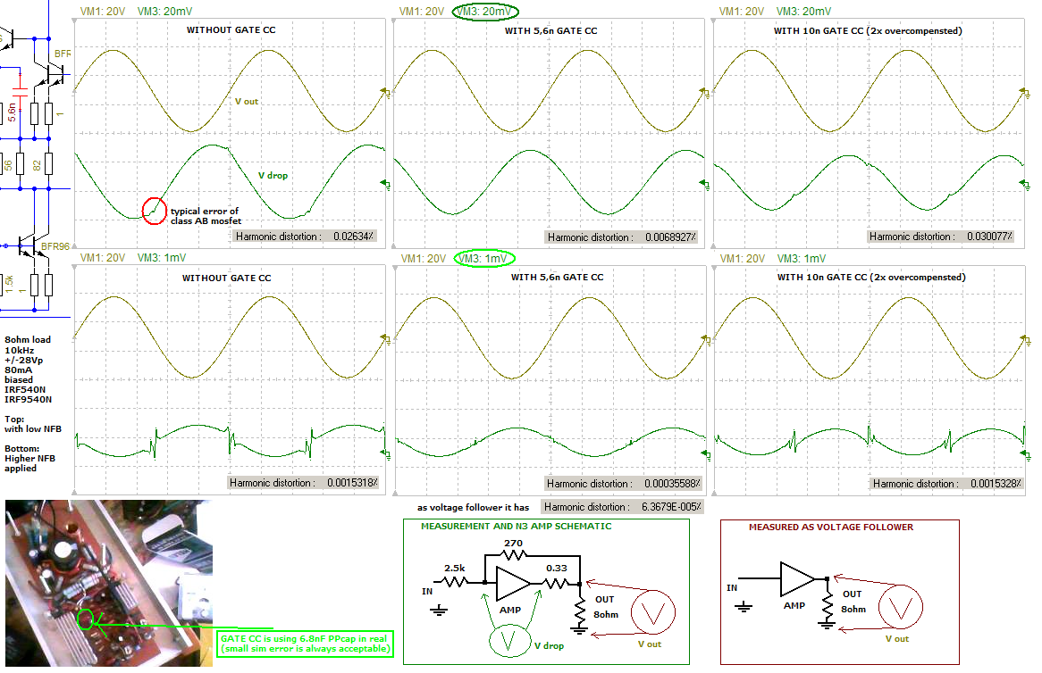
Distorsion of this wonder at 10khz/20V peak on 8R
using four output devices.
Attachments
Hello! banat
I think that when powered + -55 in it can issue 125 W, see[FONT=Arial, sans-serif]
National Semiconductor, Application Note 1645, Troy Huebner, May 2007[/FONT]
best regards
I think that when powered + -55 in it can issue 125 W, see[FONT=Arial, sans-serif]
National Semiconductor, Application Note 1645, Troy Huebner, May 2007[/FONT]
best regards
Hello Petr1951 !
Only 125W ? , even with five pair of K1058/J162 ? , since my schematic say K1058 - (X5) , J162 - (X5 ) !
Best Regards !
Only 125W ? , even with five pair of K1058/J162 ? , since my schematic say K1058 - (X5) , J162 - (X5 ) !
Best Regards !
Oh, my god !!!!Esperado, do you need a load at the output of that amp??
I was tired... The story was too beautiful !
Shame on me. Not so good to work by night.
With the load, distortion is AWFUL !!! (0.08%)
My apologize for the hope.
Last edited:
Hello, banat!
125 W at a supply voltage of + -55 V, and 8 ohms
at 4 ohms and voltage + -40 volts (if not stable, then the load will drop to + -35 V), the output voltage will be active for at least 20 volts R.M.S.
Р =U[FONT=Times New Roman, serif]²[/FONT][FONT=Times New Roman, serif]/R=400/4=100 W[/FONT]
regards
Petr
125 W at a supply voltage of + -55 V, and 8 ohms
while reducing the load factor of 2 the output power is usually increased by 60 ... 80%, no more than
Petr
while reducing the load factor of 2 the output power is usually increased by 60 ... 80%, no more than
Petr
Well, at least, one thing is interesting in my ridiculous mistake -i'm still laughing- it is the good phase behavior of Jfets inputs compared to BJT (noticed several times) with one added pole to the 3 basic stages.
Probably something to dig if some of you can deal with distortion. ( I'm not as experienced with Jfets than SIR John Curl. ;-)
Probably something to dig if some of you can deal with distortion. ( I'm not as experienced with Jfets than SIR John Curl. ;-)
Will try to sim-it. But, as you have seen, i'm not the best at this ;-)What do you think about performance of this CFB Amp ?
Last edited:
Got any performance results?
Preferably 'real life' but SPICE will do to compare with our old fogey 'dreams'. Complete circuit please so we can have a play too.
I posted the sim result of N2 here: http://www.diyaudio.com/forums/soli...ts-your-opinions-post3393033.html#post3393033
with this picture: http://www.diyaudio.com/forums/atta...-douglas-self-wants-your-opinions-gate-cc.png
Like I just said before to not too much dream, nothing is perfect in this earth. Here is latest N2 shot, it looks awful I don't think anyone interested after seeing 🙄, the sound is good but not perfect (I am happy with this and not dreaming any perfect one😀).
My apologies.. also for full schematic isn't public, but I may share what is public and usable.
Attachments
I learn SSA from Lazy Cat. It give distortion figure better than VSSA. How do improve compensation of this circuit? If C4 and C6 lowered a bit, although it is not oscillating normally, but when it drive into clipping it will oscillating.
(I still learn how to use LTSpice 😱)
(I still learn how to use LTSpice 😱)
Attachments
- Home
- Amplifiers
- Solid State
- CFA Topology Audio Amplifiers