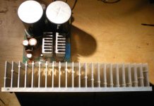
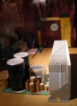
Two LM3886 chips kindly donated by TI (thanks). Power transformer 25-0-25, heatsink (27cm X 9cm X 5.5 cm), 18.000 uF 63V power supply caps.
Now the questions:
-Data sheet schematic?
-Where to buy PCB's for the chips? I'd like one per chip. I know ebay sells them but I'd like to buy the one with the best layout... I don't care about the price.
-Are the speakers safe with this amp? What can go wrong? Protection circuit, yes? no?
Now the questions:
-Data sheet schematic?
-Where to buy PCB's for the chips? I'd like one per chip. I know ebay sells them but I'd like to buy the one with the best layout... I don't care about the price.
-Are the speakers safe with this amp? What can go wrong? Protection circuit, yes? no?
Attachments
Hmmm... I'm starting to think my power supply caps are overkill.... and I need to stop reading threads about chip amps - so many different opinions! I'm much more confused now that when I started reading.
1. When people say that, they're talking about the "typical application" schematic on page 2 of this: http://www.ti.com/lit/ds/symlink/lm3886.pdf
2. Be ready for a million opinions on best layout.
3. Check for DC across the +/- jacks going to the speakers first. Test it with a resistor before you hook up speakers again. Hook it up to an old garbage speaker. Check DC again.
2. Be ready for a million opinions on best layout.
3. Check for DC across the +/- jacks going to the speakers first. Test it with a resistor before you hook up speakers again. Hook it up to an old garbage speaker. Check DC again.
Well thanks, I'm going to build it like the data sheet says. I'm aware of audiosector's minimalistic approach and I'm also aware of other opinions, like 'dead speakers sound much worse than Zobel networks'. Speakers are expensive, this lowly chip amp should pose no threat to them.
* I still want a link to buy the PCB's from.
* I still want a link to buy the PCB's from.
Last edited:
Hi cassiel, check out this Mick Feuerbacher Audio Projects
i do it like this, but only keep the big caps apart from the chip with 1 inch cables, epoxied and make a normal PS which you al ready have!!
Good luck!
i do it like this, but only keep the big caps apart from the chip with 1 inch cables, epoxied and make a normal PS which you al ready have!!
Good luck!
Hmmm... I'm starting to think my power supply caps are overkill.... and I need to stop reading threads about chip amps - so many different opinions! I'm much more confused now that when I started reading.
What makes you think that your reservoir cap values are overkill?
It is not a matter of opinion. You can (and should) simply calculate it.
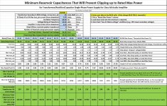
By the way, the amps at the link someone gave have stupidly-low reservoir capacitance values. He even shows evidence of that in the square wave oscilloscope photos, where the caps can't even hold up the voltage of a square wave for even part of a millisecond, and less than half of the maximum output voltage and current. Imagine what would happen during a low bass tone that last for several charging periods, which are 8 to 10 milliseconds each.
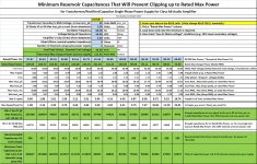
Attached are example calculations for 8 Ohm and 4 Ohm loads, with 25-Volt transformer secondary ratings.
Also attached is the spreadsheet that does the calculations. (Remove the ".txt" from the end of the filename.)
Attachments
What makes you think that your reservoir cap values are overkill?
Well I got that idea from the stuff I read here searching for info. Big caps: slow, dull sound. What I am to know? Some people say this, others say that....such a simple amp....I can't believe the disparity of opinions.
And still no-one says where I should buy the boards....ebay is only Chinese....oh well no other choice....Chinese then.
Thanks for the charts.
If you find a good layout, it's quite easy to make the boards at home. But it usually takes a few tries to get it down, the first time.
That's right, I can do it myself - it's just that I don't want to. I did entertain the idea though.
* Chinese boards are on the way
* Chinese boards are on the way
Well I got that idea from the stuff I read here searching for info. Big caps: slow, dull sound. What I am to know? Some people say this, others say that....such a simple amp....I can't believe the disparity of opinions.
And still no-one says where I should buy the boards....ebay is only Chinese....oh well no other choice....Chinese then.
Thanks for the charts.
Understandable. There are quite a few whacky ideas floating around, here.
That one about bigger caps making an amp "slow" is loosely based on the idea of the RC time constant of the cap voltage. But it's wrong, because the CURRENT is the audio signal, in the power supply caps, and the ESR of the cap would be the one that could affect the speed, in that case, and ESR is much lower for larger electrolytic caps. Or, even better would be to parallel some number of lower-value caps.
At any rate, the speed there is not too important, because the inductance of the power and ground rails will ruin it for high frequencies, anyway. The transient response speed and accuracy will depend on the decoupling caps that should be placed right at the chip's power pins. You will want a small cap, e.g. 0.1 uF X7R ceramic, right at each power pin, to a very close ground connection, and also at least 470 uF in parallel with that, as close as possible.
The main thing about the total reservoir capacitance is that it has to be large-enough to not let the voltage fall too far, between charging pulses, because then clipping will start at a lower ouput power level. So the total C value there actually sets the rated max ouput power spec. The problem would show itself most for bass ouput signals, since their waveforms can be longer than a charging interval, so the tops of those waveforms could look like high-current DC, temporarily. My spreadsheet calculates for that type of worst-case drain on the caps, and gives the value that will always keep the amp out of clipping. That actually IS a bit of overkill. But it's the only way to actually guarantee no possibility of clipping, even at max rated output power.
Last edited:
- Status
- Not open for further replies.
- Home
- Amplifiers
- Chip Amps
- Chip amp on the way