The magic number for port velocity is 10m/sec give or take depending on your reference.
Figure the SPL you will actually use and then figure your port diameter from that.
Bob
Hi,
Is usually calculated related to the drivers capabilities and that is it.
What levels you actually use and the drivers capabilities may
not match, but that is not a good reason to undersize the
port in a speaker design. In reality matching the port
capabilities to the driver capabilities is the way it is done.
rgds, sreten.
Having discussed this with Scott before, i dug into the lit, and the term TQWT (as commonly used today) was esssentially coined in Voigt's patent on the Voigt pipe.
While the discussion about terminology is endlessly fascinating, perhaps it should continue in a dedicated thread. Let's keep the TOTR (Topic-to-OffTopic Ratio) at a reasonable volume... 🙂
I think this is a fair summary for a design procedure:
Port size and length are both significant. You want to use the absolutely smallest port diameter that will support the SPL required. Determine this by looking at the port velocity. Port length is important because , as mentioned above, the are two degrees of freedom here. You can find an infinite number of pipe lengths and port lengths that will give the same Fc.
The magic number for port velocity is 10m/sec give or take depending on your reference. Figure the SPL you will actually use and then figure your port diameter from that.
Driver and port position are both important and rather touchy. After setting the stuffing to zero, move the driver to get the best suppression of the first overtone.
Now the port. There are three rather large harmonics between 700-100Hz. Move the port up from the bottom until it suppresses the middle harmonic. This produces the best FR plot. Now stuff the pipe until you get the degree of smoothness you desire.
Bob, did you mean 70-100 Hz or 700-1000 Hz? Or are you using an inverted scale?
~Tom
Bob, did you mean 70-100 Hz or 700-1000 Hz?
sorry, I indeed did mean 700-1000Hz. BTW, the harmonics in this area are real and if you do not suppress them, you will get a bump in the FR trace.
Bob
Is usually calculated related to the drivers capabilities and that is it.
Well then, I have been doing wrong all of my life!
What levels you actually use and the drivers capabilities may
not match, but that is not a good reason to undersize the
port in a speaker design
The intensity of those nasty harmonics between 700 and 1kHz is directly related to port size. Using too large a port will lead to a boxy sound. I used to use 4" ports with 8" drivers, but I now use 3" ports. The sound is now cleaner.
In reality matching the port
capabilities to the driver capabilities is the way it is done.
So if I have a driver capable of 115dB and I do not intend to use it above 100dB, I must use 115dB for all of my design parameters? Nonsense!
What levels you actually use and the drivers capabilities may
not match, but that is not a good reason to undersize the
port in a speaker design. In reality matching the port
capabilities to the driver capabilities is the way it is done.
If you can design to the max driver SPL, then life's good. But I highly suspect you'll paint yourself into a corner if you design for, say, 120 dB SPL even if that is the maximum capability of the driver.
When I actually actively listen to the music, the SPL is about 80~85 dB(C) at the listening position, 2 m away from the speakers. If we assume +5~6 dB of room gain, +6 dB for two speakers, -6 dB for 2 m away, that means each speaker produce about 80 dB SPL. So design for 90 dB to have some margin and call it done.
I would rather have a speaker that sounds good at normal listening volumes. I'm pretty sure I won't be able to hear the port turbulence over the ringing in my ears from 90+ dB SPL. 🙂
As a friend of mine pointed out: Designing a good speaker is easy. Designing a loud speaker is easy as well. But designing a good, loud speaker is quite challenging.
~Tom
Last edited:
The intensity of those nasty harmonics between 700 and 1kHz is directly related to port size. Using too large a port will lead to a boxy sound. I used to use 4" ports with 8" drivers, but I now use 3" ports. The sound is now cleaner.
Interesting. Any idea what causes the boxy sound? Why would lowering port velocity result in boxiness? How does boxiness show up in the frequency response? (Curious here).
~Tom
Well then, I have been doing wrong all of my life!
The intensity of those nasty harmonics between 700 and 1kHz is directly related to port size. Using too large a port will lead to a boxy sound. I used to use 4" ports with 8" drivers, but I now use 3" ports. The sound is now cleaner.
So if I have a driver capable of 115dB and I do not intend to use it above 100dB, I must use 115dB for all of my design parameters? Nonsense!
Hi,
What you say and what you mean aren't always the same thing.
Statements that come across as dogmatic are easy to disagree.
4" ports for 8" drivers ? You now use 3" ports ?
I'd go lower for most 8" drivers.
Related to the absolute(?) minimums ?
Well they are not and the minimum for a typical 8"/1" two
way is based on the expected power handling, efficiency,
port tuning and typical programme spectral content.
Lets say the speaker is designed for 100W programme.
A really good 8" two way for 100Wp can't handle more than
about 25W in the bass, designing it for more is pointless,
due to clipping, and port size is based on ~ 25W SPL.
Many cheaper 8" 100W drivers can't handle remotely
25W in the bass, especially higher efficiency drivers
that have higher excursion at low power but have
no excursion capability compared to lower efficiency.
Designing a speaker that the vent overloads 15dB
before the bass driver does is just **** poor design.
Like you got a driver that does 115 dB in the bass ....
rgds, sreten.
Last edited:
Interesting. Any idea what causes the boxy sound? Why would lowering port velocity result in boxiness? How does boxiness show up in the frequency response? (Curious here).
~Tom
The problem is not port velocity, it is the unwanted harmonics. With little damping in the pipe, there is a decided bump in the FR plot. Yes, you can stuff the problem away, but I like to use as little stuffing as possible. so I do what I can. Using the correct port position and reducing the size of the port serves that goal. As an aside, this is also why I do not use slot ports and the bottom of the pipe.
Bob
Hi,
What you are saying is very dogmatic and employs circular
self justifying argument, i.e. its not right for the general case.
rgds, sreten.
The problem is not port velocity, it is the unwanted harmonics. With little damping in the pipe, there is a decided bump in the FR plot. Yes, you can stuff the problem away, but I like to use as little stuffing as possible. so I do what I can. Using the correct port position and reducing the size of the port serves that goal. As an aside, this is also why I do not use slot ports and the bottom of the pipe.
Bob
I like that philosophy. Get it as clean as possible before stuffing. Then add stuffing to clean up the harmonics you can't get rid of by other means.
~Tom
fwiw, it can work with driver and port "at" both ends - the pipe below had no fill for this outdoors graph - just 1" bonded Dacron on the walls. It would be interesting to see how much useful manipulation of response could be obtained but Eminence changed their B102 long ago to a weaker magnet killing sensitivity and HF extension. note the ground plane vs on-axis response.
An externally hosted image should be here but it was not working when we last tested it.
Last edited:
The problem is not port velocity, it is the unwanted harmonics. With little damping in the pipe, there is a decided bump in the FR plot. Yes, you can stuff the problem away, but I like to use as little stuffing as possible. so I do what I can. Using the correct port position and reducing the size of the port serves that goal. As an aside, this is also why I do not use slot ports and the bottom of the pipe.
Bob
I completely agree. Design is done unstuffed to find the best geometry. MJK´s models is a must in this phase. Stuffing is the last parameter to work with.
Bob, have you tried the approach I found taming the unwanted harmonics: The short, small port is an extension of the straight pipe?
Hi
Bjørn
Bob, have you tried the approach I found taming the unwanted harmonics: The short, small port is an extension of the straight pipe?
Hi
Bjørn
No I have not. The only bottom ported speakers I have done were BR's, and I had the port tube going back into the box. I'll look at that.
Bob
fwiw, it can work with driver and port "at" both ends
I would think that having the port right by the driver would result in the port emitting sound at nearly the same SPL as the driver. This seems to be confirmed in your graph. But the port sound is off the back wave of the driver, whereas the sound that comes from the driver towards the listener is from the front of the driver. I'd imagine this leading so some rather wonky phase incoherency.
I would prefer that the port emits sound to boost the low bass and remains quiet otherwise.
~Tom
this is also why I do not use slot ports and the bottom of the pipe.
We have gotten very good results with high ratio slot vents in the miniOnkens, Dr. Moose's ML-TLs and a variation on Bob's A10.2 ML-TL.
The "R" added to the vent makes it more tolerent of dynamic changes in T/S parameters and keeps the box in the tuning range to a greater extent.
dave
I remember those; I always thought they looked pretty. 🙂 Original FT-1600s?
They can be a useful thing to have up the sleeve. > 9:1 aspect ratio will give you added R. Since I tend to pitch for near-end vent positions with MLTLs, it tends to be fairly easy for Dave & Chris to use slot or cylindrical vents as they wish, where it's a bit more work with a greater offset. Lining a stock cylindrical vent with damping material is another way -Sonus Faber are pulling that one at the moment I believe, albeit with a fancy name attached (can't say I blame them). Although usually best rear-mounted for obvious reasons in that case. 😉
They can be a useful thing to have up the sleeve. > 9:1 aspect ratio will give you added R. Since I tend to pitch for near-end vent positions with MLTLs, it tends to be fairly easy for Dave & Chris to use slot or cylindrical vents as they wish, where it's a bit more work with a greater offset. Lining a stock cylindrical vent with damping material is another way -Sonus Faber are pulling that one at the moment I believe, albeit with a fancy name attached (can't say I blame them). Although usually best rear-mounted for obvious reasons in that case. 😉
Last edited:
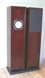
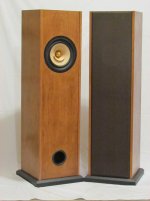
It looks like most of your speakers have a square footprint. In other speaker designs - mostly BR and sealed box - people obsess over 5/8 Golden Ratio, etc. I would imagine that a square tube would have a fairly high-Q resonance from side to side (so if the side dimension of the square cross section is 30 cm, you'd get a high-Q resonance at 1.1 kHz). Does this provide an advantage somehow? Is it easier to just deal with one high-Q resonance than dealing with several lower-Q resonances?
Would a rectangular footprint be better? You'd get two lower-Q resonances rather than one high-Q resonance. Or how about one of those cabinets with a teardrop shaped cross section? Does this violate the whole transmission line concept?
~Tom
Would a rectangular footprint be better? You'd get two lower-Q resonances rather than one high-Q resonance. Or how about one of those cabinets with a teardrop shaped cross section? Does this violate the whole transmission line concept?
~Tom
I like it Bob. 🙂 Clean lines.
I can't speak for Bob, but since most MLTLs are fairly well damped, within reason the shape of the cross section isn't a major issue. No harm in golden ratio of course, providing the driver fits (which can be an issue). Fancy box shapes are usually more marketing contrivance than having real acoustic value. Not always, but a lot of the time.
I can't speak for Bob, but since most MLTLs are fairly well damped, within reason the shape of the cross section isn't a major issue. No harm in golden ratio of course, providing the driver fits (which can be an issue). Fancy box shapes are usually more marketing contrivance than having real acoustic value. Not always, but a lot of the time.
Last edited:
- Home
- Loudspeakers
- Full Range
- Port placement in a straight MLTL