You have to model the caps as filters. If you do it is easy to understand.
The "signal" comes from the final audio power transistor. OK in a guitar pedal if might only be 100mW of power. But still that is the signal and it flows to the regulator. But between the two there is a low pass filter. What the regulator "sees" depends on the filter.
For me, a filter model would be much harder to understand. The voltage is not the signal. It's the time integral of the signal, at least when the cap is supplying the current. And the voltage rail is supposed to be held as constant as possible. It's not the signal, although it is affected by it. So the voltage-filter model seems too complicated for me to figure out, except on paper maybe.
What do you mean when you say the signal flows from the output transistor to the regulator? That would be going upstream. I can see how the voltage lowers, just upstream of the transistor, when more current is needed, and propagates "backward" to trigger the release of current. But "the signal" is the current. So, to me, it's much easier to just think of the capacitance's differential equation, or even just the basic impedance relationship (which is equivalent), which should work for both the capacitor and the regulator, relating the Δi and the Δv, as in
Z = Δv / Δi
Δi = Δv / Z
For a capacitor, the magnitude of the capacitive part of the impedance is
Zc = -1 / (2πfC)
so
Δi = -Δv(2πfC)
So we can see that if the voltage drops, which means that Δv is negative, then a positive Δi current would be released. And with a larger C, a smaller Δv would be required, to get the same Δi.
For the regulator, I don't know what form the Z would take, but it's obvious that a smaller Z in the denominator would be the same as a bigger numerator factor for the Δv, making the current change by the same amount for a smaller Δv, for a lower regulator output impedance.
I'm sure the math eventually comes out about the same, looking at is as a filter. I just have a hard time thinking of it that way.
Last edited:
So, if we put a low pass filter between the regulator and the decoupling cap, then the regulator would be able to provide "smooth" current to the cap, thus it would not mimic the signal current.
Then comes the DC observation: in a class A pedal, since DC draw remains fairly constant, can't we suppose that the final voltage in the reservoir will be held constant (slightly dropped compared to the regulator) and will be charged with smoother "pulses" from the regulator? Again the decoupling should supply musical power.
This would eliminate the tendency of the current to mimic the signal through the power cable, lowering the frequencies of any currents present on it. I realise that this does not exploit the full potential of a regulator, since the voltage of the cap could drop before the regulator is able to charge it up very fast. Or not?
Anyway, the solution Regulators > Cables > Decoupling is the most universal and easy for me. Meaning I have to provide typical 9V outputs and not worry about needing additional voltage to drop if I used a regulator inside the load. It would also be a direct fit to bought pedals I own.
I thikn I will try each solution soundwise though. I will be shocked to hear any difference between the above configuration and a regulator closer to the load, but if there isn't any, seems like I will implement the above. 🙂
EDIT: I was thinking about building sulzer regulators for various reasons. They use a 47uF tantalum along with 470nF film at their output. If I am to use decoupling networks inside the loads and cables between the regulator and the decoupling caps, do these two caps have a place? I assume that they will lower the output impedance of the regulator making the charge-up of the decoupling caps faster and more accurate. Is this correct, or is it a complete overkill to use them?
Last edited:
Sorry. I hadn't really thought about the fact that the loads were class A circuits. Most of my comments about the current were based on class AB loads.
But Class A still has sort-of-music-shaped ("i.e. max-current-minus-the-music-current") current waveforms on the return power conductor, since it "dumps" whatever current is not needed for the output back into the downstream side of the power supply.
If you want to "filter" the current flow in the umbilical, maybe you should try inserting only a small resistance, just upstream from the decoupling caps; probably 33 Ohms or less; maybe much less. Figure out the max average current that would be needed, and the voltage drop across the resistor, and its dissipation. A large cap and a small resistor can still make a low-pass filter with a low cut-off frequency, if the cap is large-enough. (You could even try the resistor in both conductors of the pair, as an experiment, maybe with half the value though, when used in both.)
But I am not sure that you would need to worry about the current in the umbilical being time-varying in proportion to the music itself, as long as it's in shielded twisted pair.
Anyway, if you use Sulzer regulators (or any other type), then yes you still need to keep the recommended caps right at the output and input.
Last edited:
Of course, my initial thoughts were about using a 10R - 220uF filter for decoupling inside the pedal. We discussed about that with ChrisA in previous posts. I think it will not make a difference in a bad way, but as you say, using shielded twisted pair may even remove any necessity (if any) of adding series resistance. I will just try each method and see if I see any difference (I don't think so).
Thanks for the link, I will certainly read that stuff!
So I will not remove the caps from the Sulzer regulator output - just needed to know about that for layout considerations. I wonder if it would be beneficial to use 47uF tantalums + 100nF film caps as decouplers, rather than 220uF electrolytic + 100nF film caps. Larger capacitance, but worse high frequency behaviour for the electrolytic - still, my frequencies of interest are not that high, maybe up to 10kHz maximum. Hmm.
EDIT: Eventually, all metal boxes will have ground potential. In theory, is it better to connect the shield of the twisted pair to the box of the effects? So that it will have exactly the potential of the box that surrounds the effect that is to be shielded? Of course only one connection there.
Last edited:
My intitial thoughts on the regulator was to provide the following:
bridge > reservoir > smoothing RC filter > regulator
So, I was thinking about splitting the dropping resistor of the RC section, in order to isolate reservoir ground from regulator ground.
My maximum load is 200mA DC. I was thinking of the following scheme, to be precise:

Do you think this is good?
And, how about the ratings of the 220uF capacitor? In a quick simulation, the current through it was about 5mA rms. Which is too low. What is its actual role, to provide a low impedance path for high frequencies? I mean, what will its role be in supplying current to the regulator? Has it to be bigger in size, in order to be able to act as a decoupling capacitor?
bridge > reservoir > smoothing RC filter > regulator
So, I was thinking about splitting the dropping resistor of the RC section, in order to isolate reservoir ground from regulator ground.
My maximum load is 200mA DC. I was thinking of the following scheme, to be precise:
Do you think this is good?
And, how about the ratings of the 220uF capacitor? In a quick simulation, the current through it was about 5mA rms. Which is too low. What is its actual role, to provide a low impedance path for high frequencies? I mean, what will its role be in supplying current to the regulator? Has it to be bigger in size, in order to be able to act as a decoupling capacitor?
The 220 uF looks like a reservoir and filter cap for the dc supply.
I didn't do the math for the reservoir functionality, but my rough estimate gut feeling would be that the 220 uF should be 1000 uF or more, for that.
As a filter, its cutoff frequency is one over two Pi RC. No calculator or pencil here so that is roughly one over .012, or about 1000 / 12, a little under 100 Hz.
I would probably want to swap the two caps' values. If the voltage is low-enough that the caps are small then I would go to a much higher value, 4700 uF as a minimum, just to make sure the cutoff freq is less than a tenth of anything I really don't want to get through.
Increasing the R would also lower the cutoff freq but you're already going to dissipate up to a watt, between the two of them. By the way, I would use at least 5 watt resistors, for up to 0.5W dissipation, so their temperature changes won't significantly modulate their resistance values.
Then again, this is all upstream from a regulator so maybe none of it is too critical.
You might also want or need a series RC snubber across the secondary. That would have to be determined with a scope.
Normally I wouldn't put a 0.1 uF in parallel with an electrolytic, since it could form an LC resonance at a high frequency. But in this case it might be good, assuming it's right at the regulator input, i.e. very physically/electrically close to it.
Thanks gootee!
Really this is why I want to use an RC filter, to drop some voltage, decreasing the regulator's dissipation. Of course these resistances will be 5W.
How about two 2200uF? The bridge reservoir plus the cap of the filter being the same?
And, do you think that this splitting of the resistance between the two reservoir rails is beneficial? Read that in Merlin's site, and seems a legit idea.
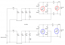
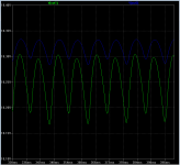
You can minimize ripple by partitioning the "Farad budget" into two equal pieces: half of the total capacitance before the series resistor, and half of the total capacitance after the series resistor.
For example, the schematic attached to post #127 has got a total capacitance of 2420.1 microfarads. Dividing it 50-50 gives less ripple (blue trace).
For example, the schematic attached to post #127 has got a total capacitance of 2420.1 microfarads. Dividing it 50-50 gives less ripple (blue trace).
Attachments
Oh, many thanks for your detailed answer!
Yes, it seems a good idea. How about using the blue arrangement but with the 20Ω resistor splitted, like in the red (two 10Ω) one? If ripple remains the same as in the original blue configuration, then I think it is better to use that approach since it can isolate the ripple current of the first reservoir from the regulator ground.
Yes, it seems a good idea. How about using the blue arrangement but with the 20Ω resistor splitted, like in the red (two 10Ω) one? If ripple remains the same as in the original blue configuration, then I think it is better to use that approach since it can isolate the ripple current of the first reservoir from the regulator ground.
You can minimize ripple by partitioning the "Farad budget" into two equal pieces: half of the total capacitance before the series resistor, and half of the total capacitance after the series resistor.
For example, the schematic attached to post #127 has got a total capacitance of 2420.1 microfarads. Dividing it 50-50 gives less ripple (blue trace).
I guess he does have a constant-current load. If it wasn't, then increasing the second cap's value would probably always decrease the ripple, since most of the ripple would probably be caused by the varying load current being drawn from the cap.
Oh, wait, I guess you meant that for a given constant total capacitance (and a constant-current load), it's best to divide the capacitance equally.
Interesting. Nice observation.
Oh, many thanks for your detailed answer!
Yes, it seems a good idea. How about using the blue arrangement but with the 20Ω resistor splitted, like in the red (two 10Ω) one? If ripple remains the same as in the original blue configuration, then I think it is better to use that approach since it can isolate the ripple current of the first reservoir from the regulator ground.
Sorry, I don't have a good feel for whether or not a resistance in the bottom leg would be better or not, and I am really short of time so I can't simulate it right now.
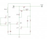
A simple circuit, something like this would be a much more accurate regulator (or DC amplifier) for 200mA just use a suitable NPN pass transistor. I use a variation of this circuit all the time. Attach this circuit onto the capacitor filter circuit above in post 130. 😉
Attachments
I am tired of thanking so much good posts. 🙂
Thank you all!
CBS240, nice circuit, a basic series regulator idea. I was planning to use a Sulzer regulator - cheap enough for my needs, and superb performance for what I need. Your circuit might need less room, so I guess that is an advantage. But have you been able to outperform a Sulzer regulator using a variation of this circuit?
It is not that my application is that demanding, I just want to build something very good to gain experience.
By the way, no output caps for this circuit? 🙂
My intitial thoughts on the regulator was to provide the following:
bridge > reservoir > smoothing RC filter > regulator
So, I was thinking about splitting the dropping resistor of the RC section, in order to isolate reservoir ground from regulator ground.
My maximum load is 200mA DC. I was thinking of the following scheme, to be precise:
View attachment 374530
Do you think this is good?
From the point of view from the regulator it doesn't make any difference, it just see whatever is on that last cap and that is also where the return current goes.
It would be a different matter if there was a ground point somewhere else in the rect/smoothing section.
Actually the way to limit the ground to the one at the final cap is excellent, but at the same time it means that splitting the R as you showed doesn't make a differnce here.
Jan
Thanks Jan!
Actually I don't want to ameliorate the regulator's performance, just to isolate the grounds as I said. I think that keeping the short current pulses from the rectifier away from the regulator is something good - can't be bad. It makes no alterations to layout, and allows the dropping resistors to operate cooler, since they share the wattage (meaning they are designed for a specific drop at a specific current - I was going to use a single 22R resistor).
Actually, this is one of the first things I learned in search of grounding techniques. Keep these dirty pulses away. As I mentioned, I found this splitting proposal in Merlin Blencowe's site. 🙂
CBS240, nice circuit, a basic series regulator idea. I was planning to use a Sulzer regulator - cheap enough for my needs, and superb performance for what I need. Your circuit might need less room, so I guess that is an advantage. But have you been able to outperform a Sulzer regulator using a variation of this circuit?
It is not that my application is that demanding, I just want to build something very good to gain experience.
By the way, no output caps for this circuit? 🙂
That circuit can be simplified using one J-fet as the feedback device and doing away with the P-ch J-fet. However, the N-ch/P-ch presents a more differential like transfer. Negative voltage regulator can be the same circuit, just reverse the polarity of the transistors. I like to use a low Gm, low noise N-ch J-fet bias at Idss (Vgs=0V). If this CCS is then cascode by a larger Gm J-fet, and the voltage source is the output of the regulator, then a very constant current will flow. Pass this current through a nice low noise resistor||small film cap to obtain a very constant low noise voltage reference.
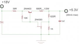
This is a small 5V regulator that requires no voltage reference (the voltage reference is GND 😀) I am using in my latest stereo amp creation to supply current for the logic control circuitry. The load circuit uses about 14mA, but will fluctuate +/- a few mA at it operates but the output voltage remains 5.3V. Why not use a typical 5.6V Zener with an EF follower? Well, this circuit nullifies the series intrinsic resistance re by means of feedback but mostly because Zeners are very noisy.
 and who wants a noisy voltage reference?
Attachments
Last edited:
So, I attach the schematic that seems to be my final choice. It is a Sulzer regulator, with a bit of filtering after the reservoir.

Any opinions? 🙂
Any opinions? 🙂
- Status
- Not open for further replies.
- Home
- Amplifiers
- Power Supplies
- Accurate voltage regulation