Hey Anyone,
If you DC couple a driver tube to an output tube you are applying additional current to grid one and the cathode is that correct? And if so does that change the bias of the output tube? Can anyone point me to an explanation of how to calculate the increased current? And how to bias the outputs?
If you DC couple a driver tube to an output tube you are applying additional current to grid one and the cathode is that correct? And if so does that change the bias of the output tube? Can anyone point me to an explanation of how to calculate the increased current? And how to bias the outputs?
You misunderstand the situation. When DC coupling is employed, the grid is at the preceding stage's anode potential, BUT things are arranged so the cathode is at an even higher potential, with respect to ground. As is usually the case, the tube is reverse biased. No additional current flows.
Thanks Eli,
So in biasing the output tube I can just bias it normally then, that makes things easier.
Thanks again, Kevin
So in biasing the output tube I can just bias it normally then, that makes things easier.
Thanks again, Kevin
Alternatively, you can couple the grid to the cathode of the preceding stage (if that is a follower), and arrange that stage so that its cathode is at the desired negative potential. Personally I feel both solutions a bit dangerous (what happens if you pull the preceding tube?) 
Alternatively, you can couple the grid to the cathode of the preceding stage (if that is a follower), and arrange that stage so that its cathode is at the desired negative potential. Personally I feel both solutions a bit dangerous (what happens if you pull the preceding tube?)
If you pull the cathode follower, the grid of the output valve gets more negative. No problem.
If you direct couple the anode, pulling it puts the following grid more positive. Not good.
Last edited:
You misunderstand the situation. When DC coupling is employed, the grid is at the preceding stage's anode potential, BUT things are arranged so the cathode is at an even higher potential, with respect to ground. As is usually the case, the tube is reverse biased. No additional current flows.
How would one acomplish such an arrangement? I thought the grids of common powertubes had to be mltiple tens of volts more negative than the cathode. Most drivertubes will put out 100+ volts at their anodes (not talking about split supplies ofcourse).
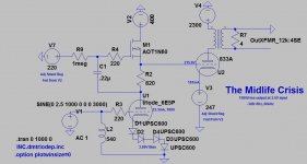
The above amp will supply current to the 833 grid above 40W output or so, as it will enter class A2, but that's another story.
Ah man, I've been stuck with my head in a PP amp all night. Offcourse SE is biased differently 🙂. Nice circuit though!
Or, you can select the operating point of the previous stage to operate at some amount of negative voltage at its quiescent point, so that it fix biases the output stage just where you want it, without then needing anything special in the cathode circuit of the output tube.
For example, Morgan Jones in his Crystal Palace amp, uses a cathode follower to drive his output stage, and he selects the operating point of the cathode follower's cathode at about -80V, which is then direct connected to the output tube's grid. (Valve Amplifiers, 3rd Edition, page 460).
For example, Morgan Jones in his Crystal Palace amp, uses a cathode follower to drive his output stage, and he selects the operating point of the cathode follower's cathode at about -80V, which is then direct connected to the output tube's grid. (Valve Amplifiers, 3rd Edition, page 460).
Have you looked at the Loftin-White circuit? That's a good way to get the basic idea understood. The following is definitely *not* a suggested circuit, but it will do for describing the DC coupling:

The first stage 6SL7's output is from the cathode of the upper tube in the SRPP. That's at +99V. That is DC-coupled to the grid of the 2A3.
The 2A3's cathode is at +144V. That puts the 2A3's grid at -55V from its cathode. That's the bias voltage on the 2A3.
The voltage from the 2A3 cathode (+144V) to its plate (+395V) is +251V. That's the 2A3's plate (anode) voltage, because the 2A3's cathode is lifted +144V above ground.
You can absolutely make a PP version of the above. Like this:

Please ignore the power supply part. Again, not a suggested circuit, just an illustration. (I built this amp years ago. It's pretty good, but the 12BZ7 is not the greatest choice for the LTP, imo.)
The cathodes of the 6CK4's wind up at about +110V, while the 12BZ7 plates are at about +90V. That -20V difference is the grid bias (Vgk) for the 6CK4 output triodes.
The above use resistors to raise the output tubes' cathodes above ground. Those resistors dissipate a lot of power (heat), which is very wasteful. But again, this illustrates the basic idea behind DC-coupling, and how the output stage is biased.
I hope that helps. Sorry if you already understood this.
--
The first stage 6SL7's output is from the cathode of the upper tube in the SRPP. That's at +99V. That is DC-coupled to the grid of the 2A3.
The 2A3's cathode is at +144V. That puts the 2A3's grid at -55V from its cathode. That's the bias voltage on the 2A3.
The voltage from the 2A3 cathode (+144V) to its plate (+395V) is +251V. That's the 2A3's plate (anode) voltage, because the 2A3's cathode is lifted +144V above ground.
You can absolutely make a PP version of the above. Like this:
Please ignore the power supply part. Again, not a suggested circuit, just an illustration. (I built this amp years ago. It's pretty good, but the 12BZ7 is not the greatest choice for the LTP, imo.)
The cathodes of the 6CK4's wind up at about +110V, while the 12BZ7 plates are at about +90V. That -20V difference is the grid bias (Vgk) for the 6CK4 output triodes.
The above use resistors to raise the output tubes' cathodes above ground. Those resistors dissipate a lot of power (heat), which is very wasteful. But again, this illustrates the basic idea behind DC-coupling, and how the output stage is biased.
I hope that helps. Sorry if you already understood this.
--
Last edited:
How would one acomplish such an arrangement? I thought the grids of common powertubes had to be mltiple tens of volts more negative than the cathode. Most drivertubes will put out 100+ volts at their anodes (not talking about split supplies ofcourse).
Like this (attached)
The 807s need -22.5Vdc on the control grid (the cathodes are essentially grounded). That sets the absolute cathode voltage of the 6SN7s. Once you know that, then figure the Vpk= 150 - (-22.5)= 172.5Vdc, and that gives you the Vpk Q-Point for the loadline. Then arrange to make the grid of the 6SN7 that much more negative than the cathode.
"Most drivertubes will put out 100+ volts at their anodes (not talking about split supplies ofcourse)".
You could, of course, "sink" the whole driver below ground potential by supplying a high enough negative voltage to the cathode of the driver.
DC coupling always means higher Vpp, since there are no "P-Channel" VTs. Either from split +/- supplies, or from a higher single ended supply. If you don't have, or want, that higher Vpp, then you'll need to AC couple.
Attachments

The above amp will supply current to the 833 grid above 40W output or so, as it will enter class A2, but that's another story.
Hi. In your setup, will the operating points of the driver tube change when the power tube goes into class A2? Or does the current source sense the change and adjust? Could the diodes at the cathode be helping out here? Sorry, all questions. Thank you. -Fred
Hi. In your setup, will the operating points of the driver tube change when the power tube goes into class A2? Or does the current source sense the change and adjust? Could the diodes at the cathode be helping out here? Sorry, all questions. Thank you. -Fred
Since I'm only now in the process of building it I can't say with absolute surety, but the LTSpice sims look very good.
The driver tube should be largely unaffected by A2 as the grid current is supplied by the AOT2N60 mosfet from the driver supply, which has a large excess current and voltage capacity (choke input supply at 405V supplying 220V to driver circuit, even at 250mA current from the driver circuit the supply is still at 330V, so there's plenty of headroom for the mosfet).
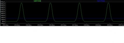
Attached is an LT Spice simulation run at full power, showing the output tube grid current (green) and the 6E5P plate current (blue). Seems like the 6E5P operating point is pretty much unaffected by a whopping 191mA of grid current being sent to the 833.
Attachments
Thank you for the explanation Magz. That sim is really encouraging since I'd like to run into class A2 with direct coupling and my situation is a small fraction of what's happening there. I made the mistake of reading your post last night and I couldn't sleep imagining what was happening with the current. -Fred
- Status
- Not open for further replies.
- Home
- Amplifiers
- Tubes / Valves
- DC coupling