Hey all,
I have two of these Hammond H1 Organ Amps, and plan on using the parts (Power trannie/chokes/output trannies) to build a new homebrew home audio amp (after I finish my Quicksilver 8417 monoblocks)...I am thinking I will likely stay with 6SN7 on front end, but may switch (modify plate resistor and cathode resistor) for a 6SL7 should I need the gain. Instead of the four 6V6, looking to go with a pair of 6L6GC or EL34 each channel, as I already have them...
Got a few questions:
Would this sound good as a home amp (not guitar)?
Anyone know the impedance of the output transformers? 6k?
Output speakers taps - 4 ohm? 8 ohm? 16 ohm?
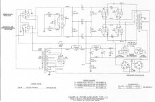
The Fixed bias...the - 18V from the -55V. Looks like the -55V is not coming from the power tranny, and no diode, but coming external from the speaker connectors? Looks like this -55V bias feed was external to this amp chassis?
This is Cathode feedback design, correct? Is this good (not familiar)? Can I modify the output tube to Cathode bias and connect the secondary windings for the speaker taps?
I have heard these amps make great guitar amps, and may end up building a guitar amp instead, but would rather build a home audio amp....
I probably should have asked these questions before buying the amps, but they were inexpensive, and still think the parts alone are worth what I paid...
I have two of these Hammond H1 Organ Amps, and plan on using the parts (Power trannie/chokes/output trannies) to build a new homebrew home audio amp (after I finish my Quicksilver 8417 monoblocks)...I am thinking I will likely stay with 6SN7 on front end, but may switch (modify plate resistor and cathode resistor) for a 6SL7 should I need the gain. Instead of the four 6V6, looking to go with a pair of 6L6GC or EL34 each channel, as I already have them...
Got a few questions:
Would this sound good as a home amp (not guitar)?
Anyone know the impedance of the output transformers? 6k?
Output speakers taps - 4 ohm? 8 ohm? 16 ohm?
The Fixed bias...the - 18V from the -55V. Looks like the -55V is not coming from the power tranny, and no diode, but coming external from the speaker connectors? Looks like this -55V bias feed was external to this amp chassis?
This is Cathode feedback design, correct? Is this good (not familiar)? Can I modify the output tube to Cathode bias and connect the secondary windings for the speaker taps?
I have heard these amps make great guitar amps, and may end up building a guitar amp instead, but would rather build a home audio amp....
I probably should have asked these questions before buying the amps, but they were inexpensive, and still think the parts alone are worth what I paid...
Attachments
Last edited:
They look like they have plenty of potential. The cathode feedback is a very nice touch IMO. I would stick with the 4 6V6 in order to maintain a proper match to the OPT. Note that the EL34 has significantly higher drive voltage requirements than the 6V6.
Should you want to get them running, and assuming coupling caps and electrolytics at minimum have been done you could do the following. Some equivalent of the 250 ohm field coil is required for proper operation, could consist of something like a 5H choke with additional series resistance to bring the DCR up to 250 ohms. I would use a choke rated for 150mA or more and a 10 - 20W resistor to start. The 5K field coil can be replaced with a 5.1K power resistor rated conservatively at 50W. Keep the fixed bias, noting that it is derived between ground and the amplifier common. All jumpers need to be in place on the speaker connectors. Transformer secondary is intended to drive 4 ohms. (Note the two original 8 ohm spks were in parallel.) Most of the parts required should be modest in cost. Something to note is that balanced input drive is required. (You could use a transformer or an LTP for phase splitting.)
Whether or not this is worth the effort depends on the quality of the OPT.
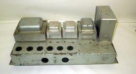
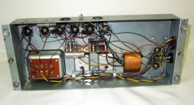
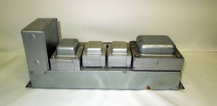
How about some pix?
Should you want to get them running, and assuming coupling caps and electrolytics at minimum have been done you could do the following. Some equivalent of the 250 ohm field coil is required for proper operation, could consist of something like a 5H choke with additional series resistance to bring the DCR up to 250 ohms. I would use a choke rated for 150mA or more and a 10 - 20W resistor to start. The 5K field coil can be replaced with a 5.1K power resistor rated conservatively at 50W. Keep the fixed bias, noting that it is derived between ground and the amplifier common. All jumpers need to be in place on the speaker connectors. Transformer secondary is intended to drive 4 ohms. (Note the two original 8 ohm spks were in parallel.) Most of the parts required should be modest in cost. Something to note is that balanced input drive is required. (You could use a transformer or an LTP for phase splitting.)
Whether or not this is worth the effort depends on the quality of the OPT.
How about some pix?
I think the bias, is gererated by the voltage drop across the feild coil of speaker. The speaker is 8 ohms according to the schematic, The feedback to the cathodes of the output tubes can be disconnected, and not used(it is not designed for high current of speaker output.), but the overall feedback loop will have to be adjusted, I don'y know what kind of frequency response you will get from the output transformer. I just did a Conn amp and it sounds great,and tests pretty good as well.You may need to add a another tube to get enough gain.
Last edited:
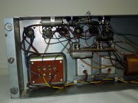
I didn't even pay any attention to that other speaker connector...now I see how some of the circuit is laid out....pics attached. The second one is in a little worse condition of this one. Still trying to figure out where that -55V bias feed comes from tho...and the B+ has a 5k resistor to ground?
Attachments
-
 $T2eC16d,!)cFId!(sToiBSOSZYm8yg~~60_57.JPG336.5 KB · Views: 547
 -
 $(KGrHqF,!n0FIrWj8LVgBSOSZ-(et!~~60_57.JPG404.9 KB · Views: 539
 -
 $(KGrHqR,!qwFIyR1WSZwBSOS,TqPI!~~60_57.JPG312.8 KB · Views: 509
 -
 $T2eC16F,!)MFIbyBZu43BSOS,F!tlw~~60_57.JPG497.7 KB · Views: 494
 -
 $T2eC16R,!zQFIcoqz)m)BSOSZnnHq!~~60_57.JPG510.6 KB · Views: 253
Last edited:
The feild coil connects the negative side of the rectifier to ground,so one end is 0V,the other is -55v, it acts as a big resistor/ choke
There is a 5K resistor to provide external power to the preamp,I am wrong about the 8 ohms, but I wasn't sure if the speakers are in series or parallel
Last edited:
The 250 ohm connects the B- to ground, and the 5k connects B+ to ground, I'll get this right sooner or later, It's getting late for me
You may be able to omit the 5k resistor,unless your B+ goes too high.
I wonder what R3 and C3 do?
You may be able to omit the 5k resistor,unless your B+ goes too high.
I wonder what R3 and C3 do?
Last edited:
and the 5k connects B+ to ground,
Forgive me for this dumb question, but is the chassis "hot"?
R3 is some kind of cathode bias balance resistor for the 6SN7 input tube?
C3 dc block? B+ on one side and -18VDC Bias on other? Why not just take C3 out all together and leave it open? What is its purpose?
The feild coil connects the negative side of the rectifier to ground,so one end is 0V,the other is -55v, it acts as a big resistor/ choke
Doesn't that -55v bias - goes to the centertap (0V since 440 - 440 each side) of the tranny?
Last edited:
Forgive me for this dumb question, but is the chassis "hot"?
R3 is some kind of cathode bias balance resistor for the 6SN7 input tube?
C3 dc block? B+ on one side and -18VDC Bias on other? Why not just take C3 out all together and leave it open? What is its purpose?
Doesn't that -55v bias - goes to the centertap (0V since 440 - 440 each side) of the tranny?
The chassis is not hot, the power transformer isolates it from the power line.
I don't know for sure,but I think C3 may possibly have something to do with preventing some kind of feedback or oscillation.
R3 might balance the cathodes somewhat,but I am not sure
Yes the -55v goes th the center tap of the hv winding,which floats independent of the chassis (ground)because it is grounded by the Field coil,through the rectifier
Last edited:
Don't omit the 5K power resistor I mentioned in my post, if you do the bias and a bunch of other voltages will be way off the mark. This resistor is sinking 56mA.
That is quite a bit of extra load,heat, wouldn't it be better to omit it, and change the other resistors to fix the voltages?
it is also designed to have a load on the preamp out on the B+ (6k resistor)
it is also designed to have a load on the preamp out on the B+ (6k resistor)
Last edited:
I think it require quite a lot of changes to the design, and in addition the operating voltages in the rest of the amplifier would then be incorrect. The resistor could be a chassis mount 50W type on an external heat sink for the purposes of experimentation.
You will need something to produce a 10k square wave, if you plan to work with feedback loops,There are some programs for computer sound cards as well as smart phones that will work for a sig gen(but not as accurate)
What circuit will you use for the amp? Willaimson(Heathkit W5m)Mullard 5-20(Leak 20)?
What circuit will you use for the amp? Willaimson(Heathkit W5m)Mullard 5-20(Leak 20)?
I think it require quite a lot of changes to the design, and in addition the operating voltages in the rest of the amplifier would then be incorrect. The resistor could be a chassis mount 50W type on an external heat sink for the purposes of experimentation.
If the original design is maintained,I would guess the preamp power needs a resistor to ground as well and some experimentation would be needed,so that the voltages are correct?
What circuit will you use for the amp? Willaimson(Heathkit W5m)Mullard 5-20(Leak 20)?
For the front end? Thinking of a cheap Edcor transformer for single ended to balanced input phase splitter into the existing 6SN7...may not be enough gain, or maybe a 6SL7 in front of the 6SN7? I have enough 6SN7's, so maybe a another in front for a Williamson setup?
I kinda haven't got that far yet....
- Status
- Not open for further replies.
- Home
- Amplifiers
- Tubes / Valves
- Hammond H1 Amp