Thanks for the link, I'll keep it for reference just in case mine come out to be fakes even though the seller said they are originals.
No doubt he stated they were originals... 😀
Of course some folks on the Internet tend to stretch the truth a wee bit. So, trust, but verify.
Or drop spencer a line....
I went ahead and changed from 4x 33000uf to 8x 15000uf because the PDF someone linked appears out of date compared to the current schematic in the store.
Thanks for the link, I'll keep it for reference just in case mine come out to be fakes even though the seller said they are originals.
Would recommend Spencer as your primary and the one you got from ebay...is your back-up....
Its very frustrating you got all your parts and you found out you have the fake JFETs😱😱....
Though frustration is part of DIY....Looking 3 to 4 weeks downtime if you dont act early😎😎
Save all your energy on your first time power-on, smokes and all time favorite HUM..😀😀😀
How can I test them if they are fake or not? i have a semiconductor tester on my DMM, it has like 4 holes with npn/pnp would that do?
How can I test them if they are fake or not? i have a semiconductor tester on my DMM, it has like 4 holes with npn/pnp would that do?
Hi Brunk,
You can check this out http://www.diyaudio.com/forums/pass-labs/241642-mystery-sj74-jfets.html and still have many others Quick search here in
DIYaudio pointing how to test your JFETs if fake or not.
At the end of the day...they will point you out to Spencer...
Based on my experience, fake JFETs still, will make your amplifier work. But you will run into several issues such,
high DC offset upon cold start, unstable bias, misleading measurements and many other issues.
One good example:http://www.diyaudio.com/forums/pass-labs/207103-f5-turbo-builders-thread-115.html Check #1143 but the problem description starts at #1122
Brunk:
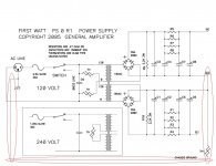
The PDF build guide uses v.1 of the diyaudio PSU board. You have v.2. It's a little different layout and may have different cap spacing. The v.2 board is a Universal board not specifically designed for the F5 and this is where a lot of your problems are coming from.
You want 8 caps. 15,000uf minimum each. 35V preferred (vs 25V). The THSA's are OK. I'd spent a few extra bucks and get 22,000 uf caps or maybe even bigger caps if they will fit the board. More capacitance is a good thing in the PSU. I am using 6 x 33,000. Dollars spent here is good. Don't go crazy though.
Remember, you are just trying to match the pass PSU schematic. The diyaudio PSU board is a universal board designed for a lot of different applications. Just match the Pass schematic using the boards. Which means (and iam generalizing here)...Transformer >rectifiers > First set of caps with bleeder resistors (3 watt 4.7K ish), second set of caps > 4 x .47ohm 3 watt resistors > third set of caps > 4th set of caps bypassed with poly caps (4.7uf or so). Trust the Pass schematic and it will guide you.
Once you figure out how it works you could just wire it yourself without a board. It's not hard. Then you can use better caps with screw terminals (i.e. computer grade) Here's what I did and how everyone helped me along the way:
http://www.diyaudio.com/forums/pass-labs/231800-jims-audio-f5-power-supply-board-3.html
Regrading the Jfets...without a curve tracer you probably wont be able if tell if they are genuine or not. They may work. Best case scenario is they work and the amp runs fine but does not sound as good as an amp with genuine jfets. Worse case is your amp catches fire. If you can I'd order jfets from Spencer. His parts have been curve traced and are genuine. It is pretty well known that the 174 jfet is highly counterfeited and pretty much no one on this forum has ever received a genuine 174 through ebay. It's worth the money to get fets from Spencer or some other reputable source here. It will not cost a lot in the grand scheme of things and it will put your mind at ease. Would you build a nice tube amp and then use $3 cheap chinese tubes in it? Same thing.
You are getting there. Learning all this stuff is more important than the end product which is the amp. I am no expert but building this amp really was a lesson in diy audio for me that has been the building blocks of everything I've done after. It'll be hard, frustrating and confusing but you will get it.
Attachments

OK looking at that schematic now makes complete sense. I had seen it before, but got lost in the parts finding frenzy lol. I have everything i need and a bit extra I'm sure, but that never hurts lol. I did get 8x 35v rated caps, 15000uf 30mm diameter. Does it hurt if i put bleeder resistors on all the caps or does it not matter?
Yes I will definitely test them beforehand. I didn't see anything in the seller's feedback about fake parts so I'm having my fingers crossed.
Would you be able to provide some answers to my questions? It would be much appreciated 🙂
Unless you get them from spencer, H_a, or other known good suppliers, it is about 99.999 percent sure they are fake. Off of ebay, its probably closer to 100%. These fets are not being manufactured anymore by Toshiba, and are heavily faked. Finger crossing wont help. Measure, throw away, contact spencer...
Russellc
Another nubie mistake is buying non approved Pass diy stuff (boards, kits, etc. not electronic parts like you bought) off ebay, like JIMs an so forth....some folks here will tell you to "go ask jim" with your questions. This sort of business is a slap in the face to everything Mr Pass has done for us.... just saying. Stealing, plain and simple.
Russellc
Russellc
Last edited:
Yes I will definitely test them beforehand. I didn't see anything in the seller's feedback about fake parts so I'm having my fingers crossed.
Would you be able to provide some answers to my questions? It would be much appreciated 🙂
Unless you get them from spencer, H_a, or other known good suppliers, it is about 99.999 percent sure they are fake. Off of ebay, its probably closer to 100%. These fets are not being manufactured anymore by Toshiba, and is heavily faked. Finger crossing wont help. Measure, throw away, contact spencer...
Russellc
Another nubie mistake is buying non approved Pass diy stuff (boards, kits, etc. not electronic parts like you bought) off ebay, like JIMs an so forth....some folks here will tell you to "go ask jim" with your questions. This sort of business is a slap in the face to everything Mr Pass has done for us.... just saying. Stealing, plain and simple.
Russellc
Yes this is why i went strictly with the DiyAudio deluxe chassis, F5 boards, and universal PSU board. I would rather have the official design and support both DiyAudio and Mr. Pass' efforts.
I'm going to take a chance on the FETs, worst case i lose $40 and some time.
OK looking at that schematic now makes complete sense. I had seen it before, but got lost in the parts finding frenzy lol. I have everything i need and a bit extra I'm sure, but that never hurts lol. I did get 8x 35v rated caps, 15000uf 30mm diameter. Does it hurt if i put bleeder resistors on all the caps or does it not matter?
Just put in a 3 watt resistor in R9 and R10 on the board. Thats the spot on the board for the bleeder. Don't solder them outside the board, directly on the caps. You just need one pair of bleeders, they will discharge all the caps. The purpose of the bleeder resistor is to discharge the caps slowly after the amp is turned off so they don't shock somebody working on the amp after its powered off.
Attachments
Just put in a 3 watt resistor in R9 and R10 on the board. Thats the spot on the board for the bleeder. Don't solder them outside the board, directly on the caps. You just need one pair of bleeders, they will discharge all the caps. The purpose of the bleeder resistor is to discharge the caps slowly after the amp is turned off so they don't shock somebody working on the amp after its powered off.
OK thank you, i wasn't sure if just two would discharge all the caps or not.
Don't even bother trying the Toshiba Jfet bought from ebay in your amp. They are likely fake.
Buy from member 'Spencer' or 'h_a'
Don't use snubber on PSU.
Keratherm thermal interface pads are available from the DIYaudio store. Or use Bergquist pink.
All the advice given you so far in this thread is good. 🙂 🙂 🙂
Buy from member 'Spencer' or 'h_a'
Don't use snubber on PSU.
Keratherm thermal interface pads are available from the DIYaudio store. Or use Bergquist pink.
All the advice given you so far in this thread is good. 🙂 🙂 🙂
Don't even bother trying the Toshiba Jfet bought from ebay in your amp. They are likely fake.
Buy from member 'Spencer' or 'h_a'
Don't use snubber on PSU.
Keratherm thermal interface pads are available from the DIYaudio store. Or use Bergquist pink.
All the advice given you so far in this thread is good. 🙂 🙂 🙂
OK i wont use snubber on the PSU then, but i guess i'll have them for later or another project lol. I did buy some K-10 pads already. I have been getting alot of great advice, you guys are great! I'm still reading the F5 build thread and taking notes on first time startup and bias. Hopefully I won't make the mistake of going too fast with it!
Brunk:
BTW, your mosfets are fine. You only should (well, REALLY should) get new Jfets. You can still use most of the stuff you bought on ebay but the Jfets.
Here's why you should just order the genuine Jfets:
It's going to be pain in the *** to get the fake ones out and the new ones in after you solder them. Do you have a desoldering iron or sucker? What if you burn the board or lift a trace? And you will have to replace the kapton silpads too, they ae a one-time only deal. And you will risk stripping threads on the heatsink. And you could make a mistake when wiring it back up or ground the mosfets by accident. And you will have to bias it all over again...
Have I convinced you yet?
Brunk:
BTW, your mosfets are fine. You only should (well, REALLY should) get new Jfets. You can still use most of the stuff you bought on ebay but the Jfets.
Here's why you should just order the genuine Jfets:
It's going to be pain in the *** to get the fake ones out and the new ones in after you solder them. Do you have a desoldering iron or sucker? What if you burn the board or lift a trace? And you will have to replace the kapton silpads too, they ae a one-time only deal. And you will risk stripping threads on the heatsink. And you could make a mistake when wiring it back up or ground the mosfets by accident. And you will have to bias it all over again...
Have I convinced you yet?
Good point, I need to listen to you guys and do that then. Thanks!
Very easy to lift traces desoldering. Test them PRIOR to installing. desolder with wick, being careful not to overheat pads. Cut part off, then poke it through with heat. If a pad vaporizes, floats off, trace pulls, etc., it will require jumpering. Very easy to do. ( the tearing it up, not the repair!)
Yes, I saw what you used boardwise, my comment was to the post with "Jims boards from ebay" another posted. Your choices there are correct. Several new builders have appeared like yourself, having already bought stuff and many have bought these and other non-sanctioned boards.
They create several problems. First they are not "legal" and many members dont want to help b/c it is furthering the cause for individuals that would steal Papa's intellectual property... Other members will help, as they feel sorry for someone who has purchased them and are having problems mid build. Finally, not being a sanctioned board, no one may be familiar with "known issues".....even some of the sanctioned boards at one time have had errors, reversed part traces, etc. Generally, these problems go hand in hand with individuals like myself, who can part id, solder well, follow intructions etc., but dont have sufficient knowledge to "correct" problems with an unfamiliar board. the sanctioned boards here have been used many times and help is easier, that's all.
Russellc
Last edited:
Thanks for the advice Russellc. I do agree that those unauthorized boards shouldn't be supported because it just damages/undermines the hard work Papa and others have so graciously provided us. That said, I am trying to stick to the "original" parts/schematics the best I can, and I did see the mistake where I was trying to follow the BOM for the universal board, instead of the F5 PSU schematic lol. I have already learned alot from you guys on this thread and various build threads here. I hope to have minimal issues, but I'm sure I will so I will be sure install resistors with a raised leg and have their values facing upwards for pictures.
Is there any beneficial reason to utilize the "optional" additional PI resistors on the PSU board?
Is there any beneficial reason to utilize the "optional" additional PI resistors on the PSU board?
Is there any beneficial reason to utilize the "optional" additional PI resistors on the PSU board?
If you are building a straight F5, no. Just use the (4) 0.47ohm 3W
The 'extra' places are for a higher-current supply, such as the one for the F5T.
- Status
- Not open for further replies.
- Home
- Amplifiers
- Pass Labs
- Newbie needs advice: F5 Build parts