Hi everyone,
I am designing a power supply using a center tapped toroidal transformer in order to supply 5Adc and +-45Vdc. I am planning to use a dual complementary bridge rectifier to achieve this. I have read that the current after rectification is 1.8 times of that before rectification, so does this mean the output current rating of the transformer can be 1.8 times less? I am just trying to work out a suitable transformer to buy.
The amp this is for is class AB, 100W into 8ohm and up to 200Hz as it is to drive a subwoofer (if this makes any difference).
Any help would be appreciated 🙂
The voltage after rectification is 1.414 x the AC voltage, therefore the current has to be less.
If I remember correctly its about 0.7 x the AC current.
If I remember correctly its about 0.7 x the AC current.
It depends of the topology of the filter to be used post rectification.
If capacitor input (Surely your case), voltage raises 1.414 as katie and dad says, but the sag under load is very noticeable, and ripple may be very high at full load. Current is about the nominal of the transformer. (Supposing the rectifier can supply it).
If inductor input, voltage under load is about .9 of the AC input, but voltage doesn't sag so severely, ripple may be negligibly small and voltage varies few with current , supposing a low DC resistance in the choke, and the wright minimum load the inductor requieres.
Show us the circuit you are thinking of using.
The DC current you can draw depends on the duty cycle, but it won't exceed the AC rating and could be quite a bit less.
The DC current you can draw depends on the duty cycle, but it won't exceed the AC rating and could be quite a bit less.
The voltage after rectification is 1.414 x the AC voltage, therefore the current has to be less.
If I remember correctly its about 0.7 x the AC current.
The voltage after rectification is the same as the voltage before rectification, minus the voltages across the diodes.
The 1.414 (square root of two) factor is merely to convert the typical RMS nominal voltage rating to the nominal peak voltage, at the output of the transformer. The voltage does not change by that factor. The RMS and peak values are just different ways of looking at (and measuring) the same AC voltage.
No! Try a simple peak rectifier: when no load, output voltage is about 1.42 tiems AC RMS voltage.The voltage after rectification is the same as the voltage before rectification, minus the voltages across the diodes.
The voltage after rectification is the same as the voltage before rectification, minus the voltages across the diodes.
The 1.414 (square root of two) factor is merely to convert the typical RMS nominal voltage rating to the nominal peak voltage, at the output of the transformer. The voltage does not change by that factor. The RMS and peak values are just different ways of looking at (and measuring) the same AC voltage.
What !!!!!
The AC voltage is the RMS voltage you are referring to.
If you measure the AC voltage you will measure the RMS voltage that is quoted as the secondary voltage by the manufacturer.
If you then bridge rectify this voltage you will get 1.414 x the RMS voltage less about 1.4V which is the diode drop in a typical bridge.
Hi everyone,
I am designing a power supply using a center tapped toroidal transformer in order to supply 5Adc and +-45Vdc. I am planning to use a dual complementary bridge rectifier to achieve this. I have read that the current after rectification is 1.8 times of that before rectification, so does this mean the output current rating of the transformer can be 1.8 times less? I am just trying to work out a suitable transformer to buy.
The amp this is for is class AB, 100W into 8ohm and up to 200Hz as it is to drive a subwoofer (if this makes any difference).
Any help would be appreciated 🙂
I have no idea what a "dual complementary bridge rectifier" is, however you might find a spreadsheet that I developed to design and size power supplies helpful. It addresses things like transformer sag with current demand, ripple voltage versus capacitance of the smoothing capacitors, and other issues. How these influence the maximum (instantaneous) power output, and the long term power (thermal) limit of the amp+PS is described as well.
This is for a basic unregulated dual-rail amplifier PS, assumed to be connected to a class AB amplifier, consisting of a center-tapped secondary transformer, a bridge rectifier, and two (banks) of smoothing caps each connected between one rail and the ground.
I think this will answer your questions, and it will allow you to explore scenarios (what if I use a transformer with a higher VA/lower VA/ higher secondary/lower secondary, or larger/smaller capacitance).
One subtle point for your particular situation is that the equations behind the PS design assume that the majority of the load on the PS is drawing current at frequencies that are higher than twice the mains frequency (120Hz is how often the caps are recharged in the USA). Under that assumption current draw is more or less balanced between rails/cap banks. However for a subwoofer, it is mostly operating BELOW 120Hz. This means that the cap bank should be oversized somewhat (for a subwoofer application) as a result of the increased possibility for asymmetric current draw. If you won't be pushing 100W often, then this is less of a concern.
To download the PS design spreadsheet, see:
http://audio.claub.net/software.html
For 100 Watts (RMS) into 8 Ohms, you would need
i²(8) = 100
where i is the RMS current of a sine wave.
So that gives
i = 3.5 Amps RMS
and
i_peak = 5 Amps
So
v_peak = 40 Volts
Your Class AB amplifier will probably take at least 3 Volts of the remaining 5 Volts, leaving only 2 Volts for the maximum p-p ripple voltage.
With 45-Volt rails, and 60 Hz mains, and assuming the amp has a 3V minimum "Vclip" voltage between the amp's rail connection and its output (which could be too low), that would require a bare minimum of 21600 uF per rail, to be able to get to 100 W RMS before clipping. With 50 Hz mains, it would require at least 25800 uF per rail.
If the amp's Vclip voltage was 4V instead of 3V, that would jump to 43250 uF for 60 Hz mains and 51600 uF for 50 Hz mains. Using a slightly-higher transformer voltage, to give you a few more volts of rail voltage, will drastically lower the required capacitance.
Depending on what type of rectifiers you use, i.e. their voltage drop when their current is 15 to 25 Amps (3X to 5X the average DC current, since they only conduct 1/3rd to 1/5th of the time), and depending on how the transformer is spec'd (I will assume that the rated voltage is for full load conditions, which it might not be), you might be able to use a transformer with a 48 Volts (peak) output voltage. The output voltages are typically given as RMS voltages, so dividing by the square root of two gives about 34 Volts RMS, or possibly more, for the minimum rated RMS AC transformer output voltage that you need, from each secondary winding, under full load. I would add at least 10% to that, to account for possible low AC mains voltage, especially if it matters that you can always have at least 100 W rated max output power.
The other spec you need, for the transformer, is the VA (Volt-Amps) rating. Your Class AB amplifier's efficiency will probably be closer to 50% than 100%. I would guess 60% to be safe. But there are also other losses. So you should at least double the rated max output power of the amplifier, to arrive at the VA rating of the transformer. Therefore, a transformer rated at 200 VA to 250 VA should be sufficient (per channel).
Summarizing:
Transformer should have 34-37V rated AC RMS output voltage, under load, per secondary side,
Transformer should have 200-250 VA rating, multiplied by the number of channels it powers.
Use reservoir capacitors rated for 63 VDC (rather than 50 VDC).
Calculate the estimated minimum reservoir capacitance per rail, with either the spreadsheet or the equation that are provided in the post at:
http://www.diyaudio.com/forums/power-supplies/240955-resevoir-capacitors-chip-amps.html#post3599692
If the power supply powers two channels, double the capacitance calculated above.
Use multiple paralleled caps that sum to more than the above-calculated required minimum value. e.g. Use five 4700 uF caps per rail, instead of one 22000 uF cap.
Connect at least 1000 uF to ground, from right at the power rail connection of the active output device.
Connect a physically-small 0.1 uF (0.01 to 1 uF) cap to ground, from within a couple of mm of the power rail connection of each active output device.
No! Try a simple peak rectifier: when no load, output voltage is about 1.42 tiems AC RMS voltage.
Which is exactly what I said.
The peak voltage only changes by the rectifier drop. Before the rectifiers, the peak voltage was already 1.414 times the RMS voltage.
Last edited:
What !!!!!
The AC voltage is the RMS voltage you are referring to.
If you measure the AC voltage you will measure the RMS voltage that is quoted as the secondary voltage by the manufacturer.
If you then bridge rectify this voltage you will get 1.414 x the RMS voltage less about 1.4V which is the diode drop in a typical bridge.
If I measure with an oscilloscope, or a peak detector, then no.
What you said above is exactly what I said in my response to your original message. Your original message would have been misleading to anyone who didn't already know that peak and RMS are just two different ways of measuring the exact same voltage.
No‼, the ratio between RMS and peak is strongly dependant on the waveform, the 1.414 ratio is valid only in pure sin signals.
No‼, the ratio between RMS and peak is strongly dependant on the waveform, the 1.414 ratio is valid only in pure sin signals.
You guys are becoming irksome. We have been discussing only sinusoidal signals. RMS and Peak voltages always BOTH exist, for a sinusoidal signal (or any signal, for that matter).
Your original posts were misleading, which is why I commented. The peak value exists both before and after the rectifier. To a non-engineer, your posts implied that before the rectifier, there was only an RMS voltage, which the rectifier somehow multiplied by 1.414. But in fact, the rectifier only takes the absolute value. When followed by the caps, a peak detector is formed. The peak voltage is the SAME as it was before the rectifier and caps, minus the voltage drop across the rectifier, exactly as I first said.
If you wanted to talk about the RMS voltage across the caps, you should have said so.
The reservoir caps are high as I have a fair few 4700uF's laying around so just stuck them in parallel.
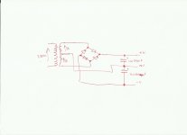
It's not two bridge rectifiers. It's a full-wave split supply, so yes, treat it as two full-wave supplies (that share a common ground).Thanks for all the comments, they're really helping. Here is the circuit I'm thinking of using. It is basically two bridge rectifiers, so can I just treat it as two separate ones?
True, but no-one refers to the peak output of a transformer.
That is exactly what you were doing, when you multiplied by 1.414.
That was my point. We DO need to refer to their peak output voltage. But they are RATED in terms of RMS. So THAT is why we multiply by 1.414. It's not because the voltage "changes".
No, I was referring to the DC voltage. The fact that it is very close to the peak voltage is just confusing the issue.
Yes, that is where the DC voltage comes from.
If the caps are insufficient after the regulator you will not see the full peak voltage as DC under load.
Yes, that is where the DC voltage comes from.
If the caps are insufficient after the regulator you will not see the full peak voltage as DC under load.
- Status
- Not open for further replies.
- Home
- Amplifiers
- Power Supplies
- Transformer Rating using dual bridge rectifier