Not again.... Will somebody please just take the same brutally accurate measurements of a SEOS and Wayne's horn and post them side by side someplace so everybody can stop talking about it?
Kinda thought you had seen 'em. I've done side-by-side measurements, and so has Matt Grant. Our measurements show general agreement, pretty much look the same. His measurements use a different compression driver than mine, but the charts are very similar except his compression driver (a DE250 clone) has a little less output in the 5.5kHz region than the compression driver I used (B&C DE250), but other than that the charts are very much the same. See below.
To tell the truth, I've seen a lot of waveguides with charts that look kind of like the SEOS, having 5dB ripple pretty far up into the passband. It's the hardest part about constant directivity horns and waveguides - Many of them have lumpy response.
To me, this has always been the grail - To get a constant directivity device that is smooth.
It seems to me that the SEOS guys are getting pretty great measurements- I've seen you refer to a throat discontinuity with these, my understanding was that they are a OSWG style throat transitioned to match the DE250- what specifically would you point out as their shortcomings, as would be reflected in measures?
Not again.... Will somebody please just take the same brutally accurate measurements of a SEOS and Wayne's horn and post them side by side someplace so everybody can stop talking about it?
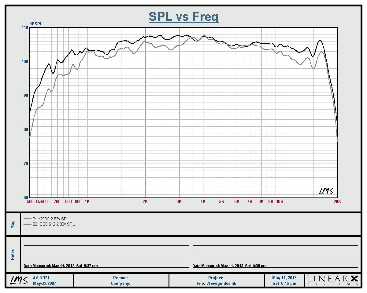
I measured an SEOS on my setup and it didn't look the same as what I have seen posted. On the SEOS the horizontals were decent, but the vertical and especially the oblique were far less impressive. Of course an OSWG, being axisymmetric, does not suffer from this problem.
I would love to see waveguides/horns all measured the same and shown in very high resolution, like I do. All of the data that John showed was heavily smoothed - makes everything look good. Then you will see the problems. Over at some other forum someone is doing something like this, and I offered to help, but there was not much interest in that. People don't really want to see the warts and all - they want nice smooth normalized data which hides almost all the problems.
I have a bad habit of overthinking things; if you've ever met an engineer who insists on the most hideously complex way to solve a problem, I'm that guy.
With a bit more thought, I wanted to offer a simpler explanation of why the JBL M2 horn looks like this:
Here's is a more concise summary of how it works:
Due to points one and points two, a horn profile that's frequently used has two stages. The first stage is used to increase the on-axis SPL. The second stage is used to control directivity. The reason that we can use two stages is because you don't need a big horn to raise the on axis efficiency, but you DO need a big horn to control directivity.
For instance, the crossover in the JBL M2 is at 800hz. Therefore, most of the horn 'gain' is needed from 800hz and up. 800hz is 42.5cm long. Due to this, a horn that's just 10.625cm long, or 4.18", will provide significant gain on the listening axis. (one quarter wavelength of 800hz, or 10.625cm.)
On the other hand, you DO need a big waveguide to control directivity. 800hz is 42.5cm long, so the *mouth* of the waveguide should be approximately 42.5cm. In the JBL M2, the mouth appears to be approximately 38cm, so we're right in the ballpark.
Ok, I hope all of that makes sense!
These two requirements - efficiency and directivity - dictate the shape of these horns:
Now if you discard the requirement for on-axis efficiency, you'll end up with something that looks like this:

intead of this:

Format is very similar. A two-way with a horn loaded compression driver on top of a 15" woofer. Crossover point is within 100hz, as it should be, because that's just good engineering.
What JBL has done is very simple; they've taken the diffraction slot of something like the 18Sound XT1086, and they've sliced that slot into four pieces and distributed it diagonally. So I'd anticipate that the JBL M2 waveguide would have similar efficiency as the 18Sound, and higher on axis efficiency than the oblate spheroidal waveguide of the Summa. But that diffraction slot comes at a price; it creates diffraction. I've also noticed that diffraction horns tend to have a directivity that widens and narrows at various points in their passband. (This may be simply due to a mismatch between the exit angle of the compression driver.)
So the science behind this horn is the same science that's been used in constant directivity horns for decades. The shape is different. But the expansion rate is basically the same. The volume of the horn is no different than what you'd expect from a conventional constant directivity horn with two stages, like the ones JBL and Electrovoice have sold for decades. It's the exit shape of the diffraction aperture that's changed.
One more bit of conjecture -
If you read the AES papers from the designer, he's put a lot of thought into intentionally varying the pathlengths from the diaphragm to the horn. By varying the pathlengths a little, you smooth the response. This is the exact same thing that happens in tapped horns, except we're talking about frequencies that are a few inches long, instead of frequencies that are ten feet long.
He uses a phase plug that's shaped like an eight pointed star to accomplish this.
Perhaps the same 'trick' is used for the exit of the diffraction aperture.
When all your pathlengths are perfectly equidistant, you run into deep nulls, and this addresses that. (This is also the reason that the Summas I'm listening to have a dip on axis; it's the symmetry that does that.)
JBL has some other patents on this; the eight sided star shape has popped up in some of their other products.
With a bit more thought, I wanted to offer a simpler explanation of why the JBL M2 horn looks like this:
An externally hosted image should be here but it was not working when we last tested it.
Here's is a more concise summary of how it works:
- A horn can be used to increase efficiency on axis, and a horn can be used to control directivity.
- Everything else being equal, a narrower horn will have higher output on axis than a wider horn.
Due to points one and points two, a horn profile that's frequently used has two stages. The first stage is used to increase the on-axis SPL. The second stage is used to control directivity. The reason that we can use two stages is because you don't need a big horn to raise the on axis efficiency, but you DO need a big horn to control directivity.
For instance, the crossover in the JBL M2 is at 800hz. Therefore, most of the horn 'gain' is needed from 800hz and up. 800hz is 42.5cm long. Due to this, a horn that's just 10.625cm long, or 4.18", will provide significant gain on the listening axis. (one quarter wavelength of 800hz, or 10.625cm.)
On the other hand, you DO need a big waveguide to control directivity. 800hz is 42.5cm long, so the *mouth* of the waveguide should be approximately 42.5cm. In the JBL M2, the mouth appears to be approximately 38cm, so we're right in the ballpark.
Ok, I hope all of that makes sense!
These two requirements - efficiency and directivity - dictate the shape of these horns:
An externally hosted image should be here but it was not working when we last tested it.
An externally hosted image should be here but it was not working when we last tested it.
Now if you discard the requirement for on-axis efficiency, you'll end up with something that looks like this:
intead of this:
Format is very similar. A two-way with a horn loaded compression driver on top of a 15" woofer. Crossover point is within 100hz, as it should be, because that's just good engineering.
What JBL has done is very simple; they've taken the diffraction slot of something like the 18Sound XT1086, and they've sliced that slot into four pieces and distributed it diagonally. So I'd anticipate that the JBL M2 waveguide would have similar efficiency as the 18Sound, and higher on axis efficiency than the oblate spheroidal waveguide of the Summa. But that diffraction slot comes at a price; it creates diffraction. I've also noticed that diffraction horns tend to have a directivity that widens and narrows at various points in their passband. (This may be simply due to a mismatch between the exit angle of the compression driver.)
So the science behind this horn is the same science that's been used in constant directivity horns for decades. The shape is different. But the expansion rate is basically the same. The volume of the horn is no different than what you'd expect from a conventional constant directivity horn with two stages, like the ones JBL and Electrovoice have sold for decades. It's the exit shape of the diffraction aperture that's changed.
One more bit of conjecture -
If you read the AES papers from the designer, he's put a lot of thought into intentionally varying the pathlengths from the diaphragm to the horn. By varying the pathlengths a little, you smooth the response. This is the exact same thing that happens in tapped horns, except we're talking about frequencies that are a few inches long, instead of frequencies that are ten feet long.
He uses a phase plug that's shaped like an eight pointed star to accomplish this.
Perhaps the same 'trick' is used for the exit of the diffraction aperture.
When all your pathlengths are perfectly equidistant, you run into deep nulls, and this addresses that. (This is also the reason that the Summas I'm listening to have a dip on axis; it's the symmetry that does that.)
JBL has some other patents on this; the eight sided star shape has popped up in some of their other products.
In my previous post I referenced an eight sided star phase plug from the M2.

^^ This is it

Dr Douglas Winker used this in his car back in the day, and I believe he helped Gary Biggs do something similar in his car as well. The asymmetry is intentional, just as the asymmetry in the M2's phase plug is. The only difference is the frequencies in question.
If you'd like to learn more, check out these threads at Diyma: DIY - reducing speaker beaming - Page 2 - Car Audio | DIYMA.com
Gary Biggs mid diffusor - Car Audio | DIYMA.com
these at audioheritage: JBL Master Reference Monitor
and the patent: Patent US20110085692 - Dual compression drivers and phasing plugs for compression drivers - Google Patents
^^ This is it
Dr Douglas Winker used this in his car back in the day, and I believe he helped Gary Biggs do something similar in his car as well. The asymmetry is intentional, just as the asymmetry in the M2's phase plug is. The only difference is the frequencies in question.
If you'd like to learn more, check out these threads at Diyma: DIY - reducing speaker beaming - Page 2 - Car Audio | DIYMA.com
Gary Biggs mid diffusor - Car Audio | DIYMA.com
these at audioheritage: JBL Master Reference Monitor
and the patent: Patent US20110085692 - Dual compression drivers and phasing plugs for compression drivers - Google Patents
Hey Patrick, can you resize your pictures so that your post is at least somewhat readable?
As for the JBL horn, I wouldn't be so quick to dismiss it. As with any speaker, it's the overall design that matters. The curves they are showing, at least on the face of it, look very smooth. I'd bet that it is a pretty good sounding speaker. Now, if you start taking apart the drivers, horns and crossover, who knows what you'd get. It's the combination that matters.
As for the JBL horn, I wouldn't be so quick to dismiss it. As with any speaker, it's the overall design that matters. The curves they are showing, at least on the face of it, look very smooth. I'd bet that it is a pretty good sounding speaker. Now, if you start taking apart the drivers, horns and crossover, who knows what you'd get. It's the combination that matters.
Hey Patrick, can you resize your pictures so that your post is at least somewhat readable?
As for the JBL horn, I wouldn't be so quick to dismiss it. As with any speaker, it's the overall design that matters. The curves they are showing, at least on the face of it, look very smooth. I'd bet that it is a pretty good sounding speaker. Now, if you start taking apart the drivers, horns and crossover, who knows what you'd get. It's the combination that matters.
Oh I'm not dismissing it at all. In fact I have a Paraline sitting here that I stole some ideas from the M2. (Methinks that all the symmetry in the Paraline is part of the reason the nulls are so deep.)
You can't have high efficiency on axis *and* wide directivity without using a diffraction slot. It was just a design decision on JBL's part.
I just learned this recently, as I was trying to get my compression driver to 'meet up' with the mids in some Unity horns here, and found that one of the reasons that I'd get a 'hole' between the mids and the compression driver was because my wall angle was wide. (IE, if I narrow the walls, I raise the output level, which allows for a lower xover point on the compression driver.)
In fact, I might even argue that it wouldn't be possible to get the compression driver in the JBL down to 800hz if it wasn't for that diffraction aperture. If I'm not mistaken, the B&C DE250 has more displacement than the JBL, and when it comes to low crossover points, displacement solves a lot of problems.
As for the size of my image, it's lifted from the patent, that's why it's hyooge.
No diffraction based horn will ever measure as smooth as one without. And no sharp edged horn will either. Maybe they "sound better" to some, but I prefer to enjoy the one that "measures best" rather than one that "looks cool".
I would expect the JBL horn to act very much like the SEOS, neither of which would measure nearly as well as one of my waveguides.
Its all about what you get used to and I prefer to set my standard to the one that is the smoothest. Some people will always like coloration, but after listening without it, I prefer to not have it.
That depends on where you do the measurement. Symmetrical waveguides will have a dip on axis. Methinks the asymmetry of the JBL is intentional. It's in the AES paper.
Dr Voishvillo, designer of this compression driver, wrote "High Quality Loudspeaker Systems and Transducers*" and you wrote "Audio Transducers**", so you're definitely attacking the same problem 🙂
* Alex Voishvillo | LinkedIn
** Amazon.com: Audio Transducers (9780972208505): Earl Geddes: Books
For instance, the crossover in the JBL M2 is at 800hz. Therefore, most of the horn 'gain' is needed from 800hz and up. 800hz is 42.5cm long. Due to this, a horn that's just 10.625cm long, or 4.18", will provide significant gain on the listening axis. (one quarter wavelength of 800hz, or 10.625cm.)
I agree in principle, but I also find that the mouth area and flare profile (shape and wall angle) significantly changes the "1/4λ" frequency. It is usually pretty close to that in a long horn where the mouth area is relatively small compared to path length, like a basshorn. But shorter horns with larger mouths like tweeters tend to have resonances at frequencies that are seemingly unrelated to their depth. It's still the same thing though, a standing wave reflection causing an impedance spike, e.g. resonance. And the first one tends to mark the frequency where the horn starts to become useful.
You can't have high efficiency on axis *and* wide directivity without using a diffraction slot. It was just a design decision on JBL's part.
I just learned this recently, as I was trying to get my compression driver to 'meet up' with the mids in some Unity horns here, and found that one of the reasons that I'd get a 'hole' between the mids and the compression driver was because my wall angle was wide. (IE, if I narrow the walls, I raise the output level, which allows for a lower xover point on the compression driver.)
In fact, I might even argue that it wouldn't be possible to get the compression driver in the JBL down to 800hz if it wasn't for that diffraction aperture. If I'm not mistaken, the B&C DE250 has more displacement than the JBL, and when it comes to low crossover points, displacement solves a lot of problems.
I agree with you, 100%.
I think one of the biggest problems for prosound horn designers is they really do need the coverage to be uniform, and where a balance must be struck between sound quality and pattern control, they must take pattern control. For one thing, they need the coverage, and for another, they need arrayability. No prosound horn will ever be used alone, so it has to "play nice" with other horns.
So I think the diffraction slot is a useful device for prosound horns. It fractures the wavefront and hurts sound quality, but it at least spreads the pattern, allowing the wall angle to confine it to whatever angle is desired. Of course, the diffraction slot makes the horn astigmatic unless the slot is put in the same place in both horizontal and vertical planes. That makes arrayability more difficult and is another cross to bear. Still, I think it is an acoustic device that is probably useful in prosound applications.
I measured an SEOS on my setup and it didn't look the same as what I have seen posted.
I thought the same thing until I realized their charts are often published with heavy smoothing or with EQ applied, sometimes both. So their charts don't look like actual raw measurements done with reasonable resolution, but if you smooth the charts enough, you can match what they are seeing.
In fact, the DIYSG guys are so used to seeing heavily smoothed measurements they sometimes don't even recognize a hires chart of their own device. I've seen a few cases where a person measured an SEOS horn and saw its true acoustic signature, but maybe scaled it so the ripple was more obvious. When that happens, regulars on that forum interpret the chart as showing a problem, when what it is really showing is the true acoustic signature of the device.
For example, look at the posts around page 7 of the "Uniform Directivity" thread:
You'll notice that there was an objection to a measurement made by a builder named Brad, but what was really happening was the chart was scaled in a way that exposed the resonances. When I rescaled Brad's chart and layed it over another SEOS chart, the match was unmistakable. So I realized right then that most DIYSG enthusiasts are accustomed to seeing heavily smoothed charts.
As an aside, I'm not sure that unsmoothed charts are "the only" way to show data, and maybe there is a benefit in smoothing lightly, like 1/12th octave. I've regularly published unsmoothed charts simply because the person interpreting the chart can easily see it's raw. They don't have to wonder how much smoothing was applied, and what details might be hidden. But I think unsmoothed charts do look "busy" and maybe 1/12th octave smoothing is more reasonable. Maybe in the future, I'll go that way. On the other hand, the more smoothing is applied, the more detail is lost and I think it's easy to present a chart that looks good, but that has hidden a lot of warts.
Here's is a more concise summary of how it works:
- A horn can be used to increase efficiency on axis, and a horn can be used to control directivity.
- Everything else being equal, a narrower horn will have higher output on axis than a wider horn.
Your simplification misses the importance of depth. Not only do narrower horns tend to have higher axial SPL due to a smaller pattern, but pathlength also determines how big a mouth is needed to control a given frequency. That's why Tractrix horns compared to OSWGs have a lower cutoff for a given mouth size. It's about pathlength- the longer the waves reside in the horn, the less they're going to wrap around the horn termination.
Your simplification misses the importance of depth. Not only do narrower horns tend to have higher axial SPL due to a smaller pattern, but pathlength also determines how big a mouth is needed to control a given frequency. That's why Tractrix horns compared to OSWGs have a lower cutoff for a given mouth size. It's about pathlength- the longer the waves reside in the horn, the less they're going to wrap around the horn termination.
That's the reason I preceded the statement with 'everything else being equal.' I wanted to stress that the length of the two horns is equal, and that the mouth size is equal.
For instance an oblate spheroidal waveguide with a 1" throat, a 15" mouth and a depth of 7.5" will have less output on axis than a 15" horn with a 1" throat, a depth of 7.5", a 15" mouth and a diffraction aperture at the throat.
SO it is possible that the Jbl horn is not a joke, but an intentionally engineered product by people who may know a little about horns. In the great irritating tradition of DiyAudio, I wonder how it sounds😉

Chec ked out the AudioHeritage site. Couple of gys over there finally got toreview and listen to them. THhey seemed to think highly of them(not too shocking), but I think at least one of them is a sound engineer, so probably not trustworthy. They do seem to suggest some heavy EQ. They do like Crown amps, PEW!
The curves they are showing, at least on the face of it, look very smooth.
They do a lot of averaging - that always makes things smoother.
That's the reason I preceded the statement with 'everything else being equal.' I wanted to stress that the length of the two horns is equal, and that the mouth size is equal.
For instance an oblate spheroidal waveguide with a 1" throat, a 15" mouth and a depth of 7.5" will have less output on axis than a 15" horn with a 1" throat, a depth of 7.5", a 15" mouth and a diffraction aperture at the throat.

Here's a pic illustrating what I mean.
1) The horn at the top left is basically how must constant directivity horns have been made for the last couple decades. There are two stages to the horn. The first stage increases the on-axis efficiency. The second stage, below it, defines the coverage angle. Both stages are necessary. You can't get the on-axis gain without the first stage, and you can't get the directivity control without the second stage.

As an aside, it occurred to me that the Paraline works this way too. Because the expansion rate in the Paraline is very slow, but it changes abruptly at the exit. So it may be possible to improve the performance of the Paraline boxes by narrowing the wall angle so that the expansion change isn't so abrupt.
2) The 2nd horn, to the right, is my rough illustration of an oblate spheroidal waveguide. The first stage for gain is absent. But there is a smooth transition from the exit of the compression driver to the the walls of the waveguide, to reduce diffraction. The transition is abrupt. If the transition was *not* abrupt, you'd have a directivity width that varied with frequency. The Peavey horn that Hughes made is basically the same curve, and the paper on it at Peavey.com has the best comparison of the types one and two that I've ever seen.
3) JBL's new horn is type 3. The diffraction aperture is still there, but it's pushed forward. So on the X and the Y axis, it's a constant directivity horn with a diffraction slot. On the diagonal axis, it's a plain ol' conical horn. (I'd have to look at the throat; it's possible that the curve is smoothed at the throat.)
4) Type four is my rough approximation of a conventional horn, like a exponential horn. In one of these horns, you get the gain on axis, but the directivity pattern varies with frequency. Whether that's your cup of tea is a subjective choice, but exponential horns are neither constant directivity nor constant beamwidth.
Hope that helps!
Last edited:
JMLC horns fall into the exponential category?
The curve isn't exponential, but they have the same issue that exponential horns have - the directivity varies with frequency.
Le Cleach has argued that his loudspeakers are optimized for European homes, which are typically smaller, where the listener basically sits equidistant between the speakers. In that type of arrangement the room sound is minimized, because you're so close to the loudspeaker.
if you smooth the charts enough, you can match what they are seeing.
If you smooth them enough then everything will look the same.
Some smoothing makes sense. I use critical band smoothing, as does Dr. Farina (Italy, inventor of log-sweep testing). He did quite a bit of research into this and found that EQing using critical bands was found to sound the most natural in a test of listeners. It also makes the most sense. Critical bands widths change with frequency, so some complex programing is required, but for my money it is the right thing to do. They are about 1/3 octave @ 100 Hz and about 1/20th octave at 10 kHz., but the change is not linear. Its a know function however.
As to all the hypothesizing about how the "horns" work, I am sorry but none of what is being said rings true to me, and I've spent a little time looking at the problem. Its just not as simple as you guys make it out to be. First, what John (Patrick, John is his real name) says about axial gain versus directivity simply cannot be true. That's because a compression driver delivers a basically flat power and if one widens the beam then the axial response has to fall regardless of how short or narrow or whatever the throat section is. The driver can deliver the power over a narrow beam - higher SPL, or a wider beam - lower SPL. How one gets to that beam width has no effect on the end result SPL - it can't. This assumes that one actually does have constant directivity of course. That's where most people cheat - the directivity is not constant.
It is true that an incoherent wave front at the mouth will mitigate any nulls seen on axis from mouth diffraction (but so does a large radius). But is this the "right" thing to do? Is an incoherent wave what is desired? To a certain extent I think it is (I did some work on this years ago), but too much can be a problem. I found that small incoherencies have audible advantages, but large ones don't sound right. The foam that I use does this to a certain extent - it randomizes the wave propagation, but not excessively. I know that the axial nulls would disappear if the mouth were random instead of round. Round is a worse case. With numerical control and injection molding one can easily do this. Its tough for a small shop however.
I was aware that it did not have an exponenetial flare, but thought it may be generally included. Thank you for the tidbit on his horns. Very interesting. I guess that leads me to a reasonable question. How great a role does the listening enviroment play on the type of horn that should be used. For an average listening room of 15 x 18, does one horn provide advantages over another?
SO it is possible that the Jbl horn is not a joke, but an intentionally engineered product by people who may know a little about horns. In the great irritating tradition of DiyAudio, I wonder how it sounds😉
Well, perhaps they're falling into the "some measurements" trap- the slots arranged as they are would be expected to show superb polars horizontally and vertically- and perhaps they're not too concerned with oblique?
- Status
- Not open for further replies.
- Home
- Loudspeakers
- Multi-Way
- JBL horn?