The Soft Start is to allow the Mains Transformer to start up.
During start up the transformer draws a very high peak current.
Normally a 3times bigger fuse allows most transformers or motors to start, but sometimes an even bigger fuse is needed, eg. time delayed fuse.
The transformer transient is complete in a few mains cycles and usually a 100ms delay is sufficient to allow a normal fuse to be fitted (avoiding the 3times oversizing).
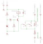
Two versions. Notice the values of the cap and resistor in the FET version. The cap can be a small poly type. The 2N7000 is a great small FET but you could use any power type such as IRF240 etc
the final soft start circuit..
Attachments
That looks OK. Only comment would be you might need to experiment with the cap value. There are a few unknowns working together such as how quick the 24 volt rail rises etc. It's fine, just make space on the PCB in case a larger cap was needed. The cap will never see more than around 6 volts DC (zener + the 0.7volt b-e drop).
Refinements... if you add a reverse biased diode (1n4148) across the 10k then the timing cap will discharge quickly back into the 24 volt rail on power off and be ready for action again immediately.
The 24 volt line... if this has massive caps then the rail will collapse relatively slowly at power off defeating the above. Sometimes a dedicated rail can work well for timer delays, something like a single half wave rectifier and deliberately undersized reservoir cap of say 100uf.
But its fine") You can go on forever thinking and adding things.
You can go on forever thinking and adding things.
Refinements... if you add a reverse biased diode (1n4148) across the 10k then the timing cap will discharge quickly back into the 24 volt rail on power off and be ready for action again immediately.
The 24 volt line... if this has massive caps then the rail will collapse relatively slowly at power off defeating the above. Sometimes a dedicated rail can work well for timer delays, something like a single half wave rectifier and deliberately undersized reservoir cap of say 100uf.
But its fine
You can go on forever thinking and adding things.That looks OK. Only comment would be you might need to experiment with the cap value. There are a few unknowns working together such as how quick the 24 volt rail rises etc. It's fine, just make space on the PCB in case a larger cap was needed. The cap will never see more than around 6 volts DC (zener + the 0.7volt b-e drop).
Refinements... if you add a reverse biased diode (1n4148) across the 10k then the timing cap will discharge quickly back into the 24 volt rail on power off and be ready for action again immediately.
The 24 volt line... if this has massive caps then the rail will collapse relatively slowly at power off defeating the above. Sometimes a dedicated rail can work well for timer delays, something like a single half wave rectifier and deliberately undersized reservoir cap of say 100uf.
But its fine
yeah that's the ting. there is always room for improvement. i will continue to do refinement's after the exam. for example i have a momentary switch that i want to use to turn the power on/off. for that i need to design a latch circuit and so on..
yeah that's the ting. there is always room for improvement. i will continue to do refinement's after the exam. for example i have a momentary switch that i want to use to turn the power on/off. for that i need to design a latch circuit and so on..
More challenges
Using a tiny low voltage momentary switch isn't that difficult or complicated. The challenge is designing really low power circuitry to control it all that can run off either just a charged cap on the secondary side or a tiny ni-cad battery.Simples
More challenges
Simples
Yes more challenges. but this time no pressure from school. it will be my hobby project after the exam.
That looks OK. Only comment would be you might need to experiment with the cap value. There are a few unknowns working together such as how quick the 24 volt rail rises etc. It's fine, just make space on the PCB in case a larger cap was needed. The cap will never see more than around 6 volts DC (zener + the 0.7volt b-e drop).
Refinements... if you add a reverse biased diode (1n4148) across the 10k then the timing cap will discharge quickly back into the 24 volt rail on power off and be ready for action again immediately.
The 24 volt line... if this has massive caps then the rail will collapse relatively slowly at power off defeating the above. Sometimes a dedicated rail can work well for timer delays, something like a single half wave rectifier and deliberately undersized reservoir cap of say 100uf.
But its fine
If i want to calculate the colector currrent that is needed for the relay coil, how is is done with my final circuit?
If i want to calculate the colector currrent that is needed for the relay coil, how is is done with my final circuit?
Because the transistor operates as a switch the relay sees essentially the full supply voltage across it. So in the diagram in post #22 it is simply VCC-1 divided by the DC resistance of the relay coil. If the supply is higher than the relay voltage (12volt relay on 24 volt supply) then you add a series resistor and just calculate using ohms law.
eg 24 volt supply, 12 volt 300 ohm relay... no its to easy that. Lets make it a 9 volt coil at 300 ohms.
Current (I) for the relay is 9/300 which is 30 milliamps. You now need to lose 24-9 volts (supply minus relay voltage) across the series resistor. So R = 15/0.03 which is 500 ohms. 470 ohms, preferred off the shelf value... near enough for jazz
I found a 24V relay so that's what i'm using.
So just measure the DC coil resistance and then calculate the current using the actual supply voltage.
I keep assuming your supply is 24 volts. Calculate for whatever the supply actually is as I outlined above
I haven't seen this point mentioned, or I have missed it; Use a pre-smoothed supply, through a diode and that will mean that when the mains is switched off, the voltage decays immediately and the relay will never still be energized if the power fails momentarily, as it may otherwise be using a rail voltage that decays slowly.
C1 should be around 100uF, with a reversed bias 1N914/4148 etc diode to relay supply, for best average results. You may need 10uF as smoothing to stop the relay chattering.
C1 should be around 100uF, with a reversed bias 1N914/4148 etc diode to relay supply, for best average results. You may need 10uF as smoothing to stop the relay chattering.
So just measure the DC coil resistance and then calculate the current using the actual supply voltage.
okay thank you.
- Status
- This old topic is closed. If you want to reopen this topic, contact a moderator using the "Report Post" button.
- Home
- Amplifiers
- Power Supplies
- Soft start