Pretty much a tube noob here but looking to learn some of the details.
I want to use the 100R/100R derived C.T. with twisted pair for all my filament socket wiring. I also want to create and revamp the current grounding to a common C.T. audio signal ground for a B+/B-.
So, currently one side of the filament (typically Pin 2) of each tube socket is grounded to the metal chassis and the other side (Pin 7) is jumped to each other socket.
In most cases there are other pins either unused (like Pin 1's) or grounded control grid pins that are also being jumped to that Pin 2 and chassis ground.
Am I correct in my understanding that if I lift pin 2 for a balanced twisted pair scheme, I will have to move those other previous chassis grounded pins to my new B- star ground?
I want to have the metal chassis to have a single ground connection to earth (AC input grounding) and all audio signal stuff common to the C.T. wire.
Things that were grounded need to remain grounded, but exactly how you do them may depend on why they were grounded. Signal return can use your new star ground. Local shielding might be better attached to ground near the valve socket. There is not a generic answer.
If your aim is reduce hum then you need to learn about grounding. Otherwise you could increase hum. The benefit of using the chassis, as they did in the 1950s, is that it is difficult to get grounding completely wrong and make bad hum. The price is that hum is always present at a low level. A separate grounding scheme, done properly, can reduce hum quite a lot but get it wrong and hum will get worse instead so you need to know what you are doing.
If your aim is reduce hum then you need to learn about grounding. Otherwise you could increase hum. The benefit of using the chassis, as they did in the 1950s, is that it is difficult to get grounding completely wrong and make bad hum. The price is that hum is always present at a low level. A separate grounding scheme, done properly, can reduce hum quite a lot but get it wrong and hum will get worse instead so you need to know what you are doing.
Thanks for the reply DF96....is it correct that the two heater pins on each socket need to be separated from those unrelated pins?
I want to wire the filaments using (2) 100R 1/2W to create a CT so I can run a twisted pair to each socket in parallel.
If that is correct then yes I will need to determine how to properly ground those unrelated pins.
I want to wire the filaments using (2) 100R 1/2W to create a CT so I can run a twisted pair to each socket in parallel.
If that is correct then yes I will need to determine how to properly ground those unrelated pins.
Thanks DF96 for confirming that.
So, maybe you or someone can help me with these other pins. I think I know what to do, but once again just looking for some verification.
Here's what end's up being disconnected after Pin 2 is separated:
6SA7GT
Pin 1 = NC
(was chassis grounded w/pin2)
6SF7
Pin 1 = Shell
Pin 3 = Cathode
(both were chassis grounded w/pin2)
6J7GT
Pin 1 = Shell
(was chassis grounded w/pin2 and the (-) side of a 10uf/25V ecap)
6SC7
Pin 1 = Shell
(was chassis grounded w/pin2)
6V6GT
Pin 1 = NC
(was chassis grounded w/pin2)
So my thinking is to connect the NC's and Shell pins to a local chassis ground tab like I plan to do with my audio shields.
On the 6SF7 cathode pin, not sure if that should go to a signal ground or stay with the pin 1 to local chassis?
And on the 6J7GT connect to my star "signal ground" buss rather than chassis ground?
First let us know whether this is a radio receiver or an amplifier, some grounding considerations will be different depending on the answer. (Looks like a receiver to me by tube line up.) The chassis is a much better RF ground than any of your mods will be, so shields, cathode, and other items referenced to chassis should NOT be moved. The filament wiring changes are OK, but the proposed change could require the addition of a ceramic cap to chassis at each socket.
Greetings from FixitLand!
If this is indeed a radio (can't imagine an amp using a 6SA7), I would urge leaving Pin 1 grounded rather than open-circuit, particularly if a metal 6SA7 (as opposed to the glass 6SA7-GT) is ever used. Pin 1 is the shell connection on a metal tube and must be grounded to be of any use as a shield. The glass tube can't use it (and may not even have a Pin 1), but might benefit from an external, grounded shield.
Take care,
--
J. E. Knox "The Victor Freak"
...Here's what end's up being disconnected after Pin 2 is separated:
6SA7GT
Pin 1 = NC
(was chassis grounded w/pin2)...
If this is indeed a radio (can't imagine an amp using a 6SA7), I would urge leaving Pin 1 grounded rather than open-circuit, particularly if a metal 6SA7 (as opposed to the glass 6SA7-GT) is ever used. Pin 1 is the shell connection on a metal tube and must be grounded to be of any use as a shield. The glass tube can't use it (and may not even have a Pin 1), but might benefit from an external, grounded shield.
Take care,
--
J. E. Knox "The Victor Freak"
First let us know whether this is a radio receiver or an amplifier, some grounding considerations will be different depending on the answer. (Looks like a receiver to me by tube line up.) The chassis is a much better RF ground than any of your mods will be, so shields, cathode, and other items referenced to chassis should NOT be moved. The filament wiring changes are OK, but the proposed change could require the addition of a ceramic cap to chassis at each socket.
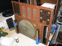
It is a radio, with 2 mic/line inputs, a phono player and a crystal record cutter (Meissner 9-1065). It's 65 years old. And yeah kinda like a receiver....LOL
It a mono machine, so not really a high-end stereo tube amp or anything.
I wanted to make it electrically safe with a new 120VAC 3 wire cord, turntable motor grounded and a fuse. I was also adding a 22k 2W bleed resistor and doing the 100R CT filament.
But if it's better to just leave all the chassis grounds alone on this thing, then I'll just leave everything the way it is and change just the filament. That would be way easier. Everything goes to chassis ground and even though I understand what's safe in SS stuff it just seems some pretty confusing methods with tube stuff, so I just want to make a safe plan before I make any of these mods.
Attachments
<snipped>
And on the 6J7GT connect to my star "signal ground" buss rather than chassis ground?
"Star" and "buss" are basically opposites. Make sure that no large OR fast-changing current will share the conductor with any ground reference point that needs to be quiet or stable or zero volts.
Even very-low-amplitude currents that are fast-changing can create large, fast-changing voltages across the conductor's very small inductance.
It is a radio, with 2 mic/line inputs, a phono player and a crystal record cutter (Meissner 9-1065). It's 65 years old. And yeah kinda like a receiver....LOL
It a mono machine, so not really a high-end stereo tube amp or anything.
I wanted to make it electrically safe with a new 120VAC 3 wire cord, turntable motor grounded and a fuse. I was also adding a 22k 2W bleed resistor and doing the 100R CT filament.
But if it's better to just leave all the chassis grounds alone on this thing, then I'll just leave everything the way it is and change just the filament. That would be way easier. Everything goes to chassis ground and even though I understand what's safe in SS stuff it just seems some pretty confusing methods with tube stuff, so I just want to make a safe plan before I make any of these mods.
I would implement only one change at a time, if possible. So if you can change the filament wiring and leave everything else the same, as much as possible, I would start with only that.
I am not sure that I understand exactly how you plan to implement your other proposed grounding change:
I also want to create and revamp the current grounding to a common C.T. audio signal ground for a B+/B-.
Where would you locate the new audio signal ground?
I would implement only one change at a time, if possible. So if you can change the filament wiring and leave everything else the same, as much as possible, I would start with only that.
Thanks gootee, I think that's a good suggestion. I will leave those other pins where they are and just breakout the one side of the heater filament and do the CT 100R filament only.
I am not sure that I understand exactly how you plan to implement your other proposed grounding change:
Sorry for that confusion, I'm sure I'm over thinking this whole thing along with some tube nubeness!
😕
What I was thinking was trying to change a bunch of soldered chassis grounds to the "star" method which would be a complete PITA and probably do nothing.
I don't even know now if I should bother with the 3 wire cord and all that?

Where would you locate the new audio signal ground?
I was thinking I would bring everything that was chassis grounded back to the secondary CT location with it's own wire or gather them together and bring them back with a heavier gauge wire to the CT location. In hindsight that's starting to seem like a huge mess!
Greetings from FixitLand!
If this is indeed a radio (can't imagine an amp using a 6SA7), I would urge leaving Pin 1 grounded rather than open-circuit, particularly if a metal 6SA7 (as opposed to the glass 6SA7-GT) is ever used. Pin 1 is the shell connection on a metal tube and must be grounded to be of any use as a shield. The glass tube can't use it (and may not even have a Pin 1), but might benefit from an external, grounded shield.
Take care,
--
J. E. Knox "The Victor Freak"
Thanks rojoknox (The Victor Freak)!
The schematic I posted for this lists 6SA7 but what's in there now is a 6SA7GT. I've looked at data sheets and most of the changed tubes appear to be the same pinouts.
There were some other differences as well from the original service manual and schematic.
i.e. 5W4GT rectifier is a 5Y3GT/G and the (2) 6J7's are 6SJ7GT's
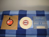
Anyway I'm having a lot of fun working on this machine, taking my time and learning lots of vintage tube restoration tips. This thing has too many features! It's not real clear I will ever get it up and fully running to the point I can get it to cut some actual vinyl (something I'd like to see). I have two blank 7" lacquers discs to test that feature with.
But I'll need to take my time and do things one step and feature at a time.
Maybe I'll get it to at least "play" a record and pick up some AM stations..
Any suggestions or comments to assist me with my confusion and dilemma's in keeping this thing all original or making it more modern, safe and sane please feel free to vent on that topic or suggest ideas or tips....
D.J.
Attachments

<snipped>
I was thinking I would bring everything that was chassis grounded back to the secondary CT location with it's own wire or gather them together and bring them back with a heavier gauge wire to the CT location. In hindsight that's starting to seem like a huge mess!
Well, maybe not at the CT. Maybe after the reservoir/smoothing caps. You wouldn't want the rectifier pulses sharing any part of any ground-return conductor. So the star ground point would usually not be upstream of the last reservoir cap.
Well, maybe not at the CT. Maybe after the reservoir/smoothing caps. You wouldn't want the rectifier pulses sharing any part of any ground-return conductor. So the star ground point would usually not be upstream of the last reservoir cap.
Well maybe this is where some of my confusion comes in....so I'll apologize now because I'll go long on this reply but sometimes it helps me out.
Then I just need some reassurance I'm on the right path and not going down some rabbit hole...LOL
This was a schematic I came across online in my research that was the closest to my unit.
It uses the same rectifier tube 5Y3GT, same xfrmr windings and same 6V6GT output stage/output xfrmr/speaker voice coil.
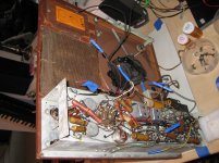
My unit has an internal speaker with field coil that is also used as the filter choke and I'm replacing the original 15/15 multi-can cap with (2) 15uf 450WV radial filter ecaps. I'm also replacing all the rest of the paper caps, resistors and wiring on this thing.
The attached schematic has the 100R divided filament scheme and uses the secondary CT as the 0V reference point with a 22k 2W bleed resistor at the filter output. I'm adding the bleed resistor and filament/heater mod.
So that creates a 260VDC B+ and B- supply rails. And that was the (B-) point I was referring to in one of those earlier posts.
So you'll notice on this attached schematic the "chassis" ground symbol (fork) is only shown at the incoming AC earth and the speaker voice coil, nowhere else.
So more confusion ensued. I thought I had grasped the idea of the B+ and 0V reference with all your ground points going to that 0V (B-). Now in my mind that creates a "floating" ground point and read this approach might improve or reduce hum and/or line noise (I did want to make some improvements in the sound quality if possible).
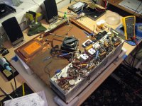
The problem was I didn't see any actual grounding to the tube chassis which is where everything on this machine is currently going. It's that 40's design.
Again thinking I could update that, some of this stuff in here is frame contact chassis ground to begin with. So changing all of that of the chassis to this 0V reference line would be a ton of work and maybe different parts & cost.
So then all that got me thinking about properly earth grounding any and all this stuff such as exposed metallic parts on this beast for safety. The tubes are actually accessible and exposed in the top left area of the case as well as the control panel switch plate, the turntable platter and motor assembly.
The whole unit is housed in a covered wooded hinged suitcase box.
OK so there are metal parts mounted in this case/box that can be touched and potentially dangerous?!
So then I started thinking what to do to make it rock solid safe.
I update the primary side of things with a 3 wire/grounded cord, new fuseholder (1.25A), MOV across line/neutral and a Y2 safety cap from line to earth ground. Surge protected, safety capped and fused. I feel that should be a good design.
The turntable motor is rubber isolated from the platter assembly and is also 120VAC with a case ground tab. So I'll run a separate green ground wire to AC earth for that and put the motors separate power switch on the fused side with the xfmr primary. There's a separate power switch for the turntable motor which is after the units main power switch mounted over on the tube chassis control panel. That seems good.
Run a separate green ground wire from the tube chassis to AC earth ground along with that speaker ground side of the output transformer. Do a bond ground check on everything to ensure good grounding of the entire unit.
If I understand all this and I move all those chassis grounds from the tube chassis to a star ground method using that 0V secondary CT after the bleed resistor as ground....does that CT still get connected to the chassis or AC earth ground at one place somewhere???
And if that's the case, then I think I should just leave all those grounds on the chassis as they are and treat the chassis as a ground plane bonded to AC earth in one location.
Wow....too much coffee and free time, my head hurts now!


Attachments
I wish you had told us that from the beginning. My advice now is to leave it as it is, unless you know how to do valve RF circuits. The heater line may need decoupling between certain valves, and a balanced heater just doubles the effort. You don't want to reduce hum but replace it with whistles!djmeverett said:It is a radio
One thing I have learned, here, is to always listen to DF96.
My advice, then, would be to replace all of the electrolytics before even powering it up, and replace the resistors, then insert a light bulb tester in the AC mains and see what you've got.
My advice, then, would be to replace all of the electrolytics before even powering it up, and replace the resistors, then insert a light bulb tester in the AC mains and see what you've got.
If this was a more modern radio using 7 pin miniature tubes, I'd swap out a 6BE6 and a 6BA6 with 3BE6 and 3BA6 respectively. I don't think they made a 3SA7 or 3SF7. I'd leave their grounded heater pins tied to ground, preserving the RF bypassing as designed and built. And rewire the heater lines so the rest of the set's tubes' heaters are not grounded, and still fed by the 6.3VAC heater winding. And connect one side of the heater winding supply to the 3BE6 and the other to the 3BA6. The 3BE6 and 3BA6, effectively in series with the midpoint grounded, form a voltage divider to create a centertap to make both heater supply windings look like 3.15VAC above ground.
Last edited:
I wish you had told us that from the beginning. My advice now is to leave it as it is, unless you know how to do valve RF circuits. The heater line may need decoupling between certain valves, and a balanced heater just doubles the effort. You don't want to reduce hum but replace it with whistles!
No not looking to degrade anything at all DF. Just the opposite. Not sure what I was supposed to tell you beforehand that has now changed your mind?
I'm usually easily convinced if it ain't broke....blah blah blah.
Not even opposed to leaving the heater circuit alone either. Just something I had read online and thought while I was in there what the heck....but there are plenty of other things that need attention.
But sorry if you got the wrong impression or background.
I may be going overboard in my thinking and planning and making more to do over nothing.
I may have now gleaned a little vague knowledge from you that involves the radio section in all this and even though your comments tend to be a little generic and vague I know exactly what your saying.
But part of this for me has to do with learning some of the detail nuances of tube circuits and I thank you for that!
This unit certainly has all of the above.
But part of the fun for me with this hobby is the planning and research as well as this forum chatting.
I'm not under any time pressure or constraints, I'm just taking my time, being cautious, being safe and having fun. Not trying to reinvent the wheel or create a high end tube amp here. Most of it is just challenges and tips in replacing old vintage components with something safer and better to get a 65 year old box in good working condition. This thing has some family history and it's 10 years older than I am and it is what it is....
I certainly enjoy chatting about this with you and getting your comments...gootee as well. No agenda, no pressure just enjoyable chat, discussion and thoughts.
One thing I have learned, here, is to always listen to DF96.
My advice, then, would be to replace all of the electrolytics before even powering it up, and replace the resistors, then insert a light bulb tester in the AC mains and see what you've got.
Sounds like I have gotten the right people to get advice from on tube circuits ..so thanks for that and all your help!
I have a DBT and adequate test equipment and a healthy respect for the electrical aspects of working on these things, so I'll certainly do a thorough and safe testing process after replacing these caps and resistors and see what I get.
Right now I'm just getting a handle on everything...and some due diligence in a plan of attack, so I hope you both have some renewed confidence in my ability and understanding.
If there's anything else about this you need or want to know just ask...I posted the schematic earlier in the hope that contains most of the info.
On a side note.....if I leave everything as is would it still be a good idea to put that bleed resistor in?
If this unit is rare or valuable then it might not be a good vehicle for initial learning about valve radio or audio. Bear in mind that any changes apart from sympathetic repairs could destroy its value. Up to you, but you might be better to start with something common and cheap. Lots of old radios available. Then come back to this when you have more experience.
- Status
- Not open for further replies.
- Home
- Amplifiers
- Tubes / Valves
- Changing to twisted pair heater from one side grounded