I'm just curious
regarding woofer inductors
you have 2x 5mH in series
with a zobel between them
does that work like one 10mH with zobel on one half 😕
regarding woofer inductors
you have 2x 5mH in series
with a zobel between them
does that work like one 10mH with zobel on one half 😕
Just take your outside dimensions and subtract whatever the panels actually measure.
So if panels = 22mm and front baffle = 40mm, and
outside height = 580mm
outside width = 325mm
outside depth = 590mm, then
inside height = 536mm
inside width = 281mm
inside depth = 528mm, and
net cabinet volume=~ 75.5L
How many distance have I to left:
-R tube lenght 274mm -22mm (thick rear cab) = 252mm inside the cab so if I left half brace of horizontal brace is 264mm, can be enough 12mm?
-If I chamfer the woofer (like the mid-woofer) front woofer cab thick is 40mm less -8.5mm to chamfer the woofer = 31.5mm, woofer depth is 80.67mm -31.5mm = 49.17mm inside the cab, if I left 70mm can be enough?
1st question is
-BR ube lenght 274mm -22mm (thick rear cab) = 252mm inside the cab so if I left half brace of horizontal brace is 264mm, can be enough 12mm?
Attached the real placement of tweeter & mid-woofer, the placement you posted is wrong
Absolutely correct. I posted the old one. Sorry.
I'm hoping pictures will answer your last few questions.
You can still change a wee bit here and there but below is probably what I'd do.
I changed the minimum amount of wood between each circular cut-out and a cabinet panel and between each of the different circles from 25mm to 20mm. I thought that would suffice.
I don't know how to draw a port flare in that program so I just made the end a bigger diameter. I'm giving the port a fair amount of room to breath and then glueing bracing to it to make it a part of the matrix structure. The driver also gets a fair amoung of breathing room behind it too.
Second picture is from a top view and 3rd is exploded. Depending on how you put the cabinet together, notice that there may be a certain order to construction that is necessary.
Attachments
I'm just curious
regarding woofer inductors
you have 2x 5mH in series
with a zobel between them
does that work like one 10mH with zobel on one half 😕
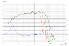
No, I think it works like a 3rd order electrical with a resistor added after the cap.
First graph shows the FR with 1 x 10ohm plus 150uF and 2R as a zobel. Completely different response.
The 3rd order xo gave me the roll-off I wanted but it also gave me 2 unpleasant peaks below it (2nd graph). The series LCR in parallel takes care of the first peak (but requires some large values - 3rd graph) and the 2R after the cap tames the 2nd one (last graph).
Attachments

First graph shows the FR with 1 x 10ohm plus 150uF and 2R as a zobel. Completely different response.
I like the first graph better ... maybe only needs small adjustment
try smaller zobel cap and bigger resistor instead
and if 1x10ohm is meant to be 10mH, maybe its too big
and maybe L4 on midrange is too big with 12mH, creating the hump at roll off
might try put a series resistor on it
and then the series cap may end being too small, as a result
See if these help.
You may need to squish in the sides of some of those circular cut-outs just a little bit to leave the 20mm of wood they need between them.
Wouldn't hurt to double check things - my brain is feeling pretty tired today. 😱
You may need to squish in the sides of some of those circular cut-outs just a little bit to leave the 20mm of wood they need between them.
Wouldn't hurt to double check things - my brain is feeling pretty tired today. 😱
Attachments

theres a small suckout at mid/tweeter xo point
maybe mid series coil is a bit big
Not much I can do about that one. That's the null in the FR of the driver.
Thanks for the xo input btw. I appreciate it.
I tried a lot of different things on the woofer before settling on the current values, but I'll try some more and see if I can't reduce the values and/or the number of components it's using.
See if these help.
You may need to squish in the sides of some of those circular cut-outs just a little bit to leave the 20mm of wood they need between them.
Wouldn't hurt to double check things - my brain is feeling pretty tired today. 😱
Forgot to ask the distances of attached pic, TIA
Attachments
That's the null in the FR of the driver.
I thought 'the deep null' should disappear when phase is reversed on one driver ?
Forgot to ask the distances of attached pic, TIA
I figured that out too. This should help. Again the circular cut-outs could be stretched a bit if you want to so that those repeating measures of 8 and 22.5mm are 5 and 20mm, but it's fine too as shown.
By the way, the dimensions I've provided mean that the braces are just going to be glued to the surface of the cabinet panels which is good as long as the are solidly glued. However, there is a stronger construction technique called a dado in which you make a cut-out or a trench in the panel and then you fit the bracing into those. There are then 3 sides that are glued together instead of just 1. Rough picture attached. I'd make the dado about 5mm deep and therefore the height and width of each bracing panel would need to be 10mm longer.
Attachments

I thought 'the deep null' should disappear when phase is reversed on one driver ?
Maybe I used the wrong word. The mid has a naturally occurring dip in its response at about 2200Hz, or maybe I should say a peak at 1800Hz and another at 3000Hz. I did manage to flatten those out more or less but the dip remains. Still it's only 2dB.
Of course I could attempt to lower the xo point and use more of the tweeter output but I don't like the way the 3rd, 4th and 5th harmonic distortions rises sharply below 3000Hz on that Seas tweeter (2nd graph). Really, I would prefer to move the xo up a little higher still but then the off-axis behavior of the mid starts to become a bigger problem. The 2dB dip, well actually 2 x 2dB dips in the simulation is what I thought was the best compromise.
When the polarity is reversed on the mid, the reverse nulls are indeed nice and deep. (grey line on last graph, top)
Also, I tried a number of other combinations on that woofer xo but none of them give me as flat a response. Many push the peaking below the xo frequency even higher so that it becomes louder than the mid and I have no room to work with that - there is absolutely no padding right now on that mid and only a little on the tweeter.
The xo employs some big values but that's not unheard of. The slopes are almost all exactly 3rd order acoustical and the overall FR is +/- 3dB (or is that +/- 1.5dB?) so I'm pretty happy with it as it stands. And since it's modeled with about 3dB of baffle step, if in reality it ends up as a little more then that can be adjusted by ear with added resistance to the mid and tweeter.
Attachments
I figured that out too. This should help. Again the circular cut-outs could be stretched a bit if you want to so that those repeating measures of 8 and 22.5mm are 5 and 20mm, but it's fine too as shown.
By the way, the dimensions I've provided mean that the braces are just going to be glued to the surface of the cabinet panels which is good as long as the are solidly glued. However, there is a stronger construction technique called a dado in which you make a cut-out or a trench in the panel and then you fit the bracing into those. There are then 3 sides that are glued together instead of just 1. Rough picture attached. I'd make the dado about 5mm deep and therefore the height and width of each bracing panel would need to be 10mm longer.
If I cut-out or trench the front panel will be 4 sides glued togheter so better rigidity?
I wanna be sure: bracing thickness is 20mm?
Woofer measures 198mm + 4mm chamfer one side + 4mm chamfer other side = 206mm, you calculated 281mm -10mm one side - 10mm other side = 261mm, I guess is OK?
Woofer data-sheet http://www.europe-audio.com/document.asp?document_id=2388&link=datasheets\sba\SB23NRXS45-8.pdf
Last edited:
If I cut-out or trench the front panel will be 4 sides glued togheter so better rigidity?
For the bracing to be effective it must be glued to the cabinet panels including the front baffle. Using a dado means that the bond between the cabinet and the brace will be stronger.
I wanna be sure: bracing thickness is 20mm?
Given the size of your cabinet, I think 10mm will be ok. That's the assumption I've been working under.
Woofer measures 198mm + 4mm chamfer one side + 4mm chamfer other side = 206mm, you calculated 281mm -10mm one side - 10mm other side = 261mm, I guess is OK?
See attached for what I was thinking. It depends on how deep the chamfer is. Here I've made it 25.4mm, so there is actually about 15cm left over on each side.
Attachments
Looks like a terrible xo you have there. Do not rely on the flatness of the simulated fr and do not think you can throw anything as long as it looks good. Check filter for each driver done by pro and learn from it. Any components you throw has effect on phase and that is the real devil not the flatness.
- Status
- Not open for further replies.
- Home
- Loudspeakers
- Multi-Way
- Help for 3 or 4 way loudspeaker