This wasn't a particularly heavy duty PA amp by the looks. It was also designed to run from a car battery, so the power supply was 13.8V and the speaker connected via a transformer (with 8 ohm and 100V taps), and a feedback winding! Rather odd... I'd have thought it cheaper to use an SMPS than an output transformer!
Anyway, 30W should be adequate for me. I have a 2xLM3886 based amp which is on 25V rails, and that produces plenty of sound 🙂 The only reason Im building this, is because I want to build a discrete amp 🙂
Anyway, 30W should be adequate for me. I have a 2xLM3886 based amp which is on 25V rails, and that produces plenty of sound 🙂 The only reason Im building this, is because I want to build a discrete amp 🙂
I might have a better case candidate now. I got a Technics SU-Z55 from freecycle. The original owner said it wouldn't power on. Well, it powered on but the right channel was heavily distorted. After a poke about and investigating a quite warm 2SD592A - no sound at all 
Hi jaycee,
Wow, I didn't realize that 60 W PA amp .... wasn't.
Still, I imagine you would be doing no worse than most of the commercial product out there. I don't read you as a head banger either.
Allow me one comment though. Joy may be found with systems around 150 wpc (+3 dB headroom also) and a pair of large speakers. This is an occasional thing, but satisfying. Puts a grin on one's face when the music is up to the job. I'll admit that most times, a 30 ~ 50 wpc system would do very well.
I would suggest that you also build a SymAsym at some point. That is one very good sounding little amplifier. I used MJW0281A and MJW0302A for outputs and Japanese transistors for everything else. My bias current for lowest THD ended up lower than most. There are several variants of that basic circuit now, my next build will use J-Fets for the diff pair. It will work well anywhere from 25 to 35 volt supplies. I would recommend tending towards the 35 V end as that was what it was really designed for.
Check out the threads for this amplifier if you have time. Poke around past the middle and closer to the ends.
-Chris
Back To The Future 50 (BTF50)
Actually I was looking for Frugalamp/Symasym schematics and then then found another OStripper project, the BTF50! 😀
Does anyone have the simulator files for BTF50?
Fortunately, it was possible to find the schematics and layout examples, so those are in the attachment.
Actually I was looking for Frugalamp/Symasym schematics and then then found another OStripper project, the BTF50! 😀
Does anyone have the simulator files for BTF50?
Fortunately, it was possible to find the schematics and layout examples, so those are in the attachment.
Attachments
Simulation file.
I think this is the simulation file.
--g annaji
Like to thank Daniel for uploading old missing files.
I think this is the simulation file.
--g annaji
Like to thank Daniel for uploading old missing files.
Attachments
Last edited:
Looking recently for information to construct a simple set of amplifiers to complete my HTPC amp , I attempted to discuss the issue on the DX thread.
Since I was forced to modify the layout because of my application (stealth amp retrofit) , I could not use the DX board. I also have a surplus of 2sa992's , mje/ and other on- semi devices.
The amp in question was originally an RCA application note (1972)...
amplifiers
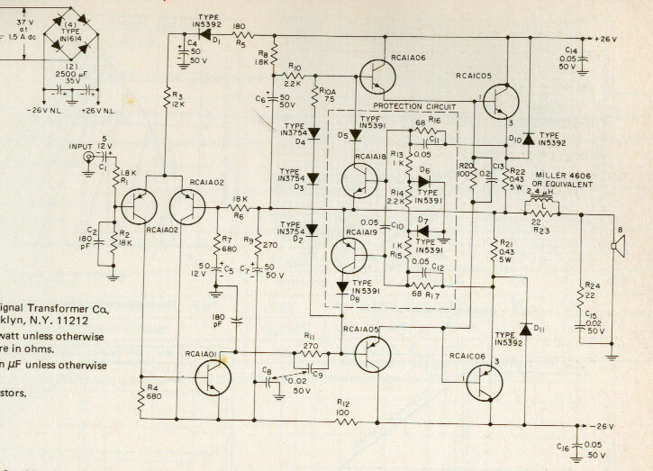
As most of us know , this is the "original" .. skillfully upgraded and modified by "uncle charlie" , aksa , and too many others to count.
Also very interesting is that on the other pages (link above), many of our DIY SS amps found their beginnings in these RCA designs.
This thread is to address ALL modifications that are possible to this simple topology (even minor ones). In other threads it was suggested
that the use of new high Ft devices would render both the sound and stability of this amp unusable AND that if a constructor does modifications,
strays from the path,or asks questions, they will learn nothing !! 😕
I know this to be false , as many clones of the RCA exist of world class performance that DO use modern parts. (I already have 2 that are 1 year old 🙂 )
Who can upload the genuine datasheet from RCA of this diode (1N3754):
http://www.radiomuseum.org/images/tubephoto_klein/1n3754.jpg
thank you therefore.
No problem. Attached is the genuine RCA datasheet for 1N3754.Who can upload the genuine datasheet from RCA of this diode (1N3754):
http://www.radiomuseum.org/images/tubephoto_klein/1n3754.jpg
thank you therefore.
The forward voltage drop is unusually large. That one was popular in radios for a "clamp diode" so 1n4007 doesn't replace it.
See also ebay item # 400329897502 for the 1N3754 hangout in Bonner Springs, KS, USA.
Substitutes?
A "1/2w" rated blue-white ingan led ~3v may (or may not) work instead of the series three 1N3754 on that schematic. High voltage zeners used as ordinary diodes may (or may not--check datasheet) have a Forward voltage drop as large as 1N3754. About twice as many of the smallest FR diodes may (or may not) do it. Even BA159 might work. Or there's the option of using transistors as diodes. Unfortunately, it looks like we'd have to physically measure the real unit and compare to the real replacement if an exact mach is wanted.
Attachments
Last edited:
Member
Joined 2009
Paid Member
Wow, this thread is a blast from the past - from the days when the bootstrap amp was king on this forum, before the CFA amp took it's crown (for the time being).
We had AKSA, DX, my TGM1, OS amps, MJL2119's amps - there was a flurry of stuff going on back then.
We had AKSA, DX, my TGM1, OS amps, MJL2119's amps - there was a flurry of stuff going on back then.
Thank you very much!Dear Daniel, I found two more files in my BTF folder. --gannaji
I think that this thread and the BTF50 is really great for showing a place to start.Bigun said:Wow, this thread is a blast from the past - from the days when the bootstrap amp was king on this forum, before the CFA amp took it's crown (for the time being). We had AKSA, DX, my TGM1, OS amps, MJL2119's amps - there was a flurry of stuff going on back then.
On first glance, there seems to be a few places where higher performing active parts cost same or less. And I see some probable locations in the power circuit that could make use of a diode drop, either at small signal like Hafler DH220 or at large signal like my TDA7293 project which doesn't need any topology changes (it uses one external CRC power supply). Those sorts of little mods (transistor selection and virtual dual mono power) could probably get it, sonically very competitive.
No problem. Attached is the genuine RCA datasheet for 1N3754.
The forward voltage drop is unusually large. That one was popular in radios for a "clamp diode" so 1n4007 doesn't replace it.
See also ebay item # 400329897502 for the 1N3754 hangout in Bonner Springs, KS, USA.
Substitutes?
A "1/2w" rated blue-white ingan led ~3v may (or may not) work instead of the series three 1N3754 on that schematic. High voltage zeners used as ordinary diodes may (or may not--check datasheet) have a Forward voltage drop as large as 1N3754. About twice as many of the smallest FR diodes may (or may not) do it. Even BA159 might work. Or there's the option of using transistors as diodes. Unfortunately, it looks like we'd have to physically measure the real unit and compare to the real replacement if an exact mach is wanted.
Thank you very much for the datasheet and the additional advices regarding replace.
BTW - I am looking for the first commercial advertisement (announcement) from formerly's brand RCA (from any electronic magazine published in the early sixties) concerning the 2N3055 and the first RCA application notes.
Maybe you have an idea - go to post 111 about
http://www.diyaudio.com/forums/soli...dels-quasi-complementary-power-output-12.html
Hi Os,ABSOLUTELY my intentions , not to compete with Carlos , or to steal, that is why I try to catch all mistakes - and pay close attention to details.
The FINAL version with no errors.. (almost sure):
BTF50 (back to the future) is the name , since it uses the MJE's for drivers, one could use the MJL21193/4 and drive a sub with that one. Make 5 more with the $1.40 NJW's and stack all of them side by side for a dandy 5.1 HT setup. I KNOW they have good PSRR (have 2 already), so a single 25-0-25VAC 6-800VA trafo would do for all 6 channels.
[ ALL references to DX are removed ] I will begin to generate a PDF with BOM , tips . schema ,and other helpful stuff and it will be done soon.
OS
Know this thread has been dead for a long time, but was wondering if this is the final layout and if you or anyone else has built it? Its quite compact and has inbuilt PS, was wondering if I could make use of it for a boombox.
regards
Prasi
edit: where does the speaker return go? directly at the chassis star?
Last edited:
Will this boom box have a mains cord or not?PS, was wondering if I could make use of it for a boombox.
It probably won't be "cordless" if you use a Class AB amp this big. That could be a determining factor.
The board's star ground that is located in-between the two biggest caps.edit: where does the speaker return go?
Will this boom box have a mains cord or not?
It probably won't be "cordless" if you use a Class AB amp this big. That could be a determining factor.
The board's star ground that is located in-between the two biggest caps.
Thanks Daniel for the reply. Its not for a "picnic" type of boom box that u can carry around, but for fixed in-house BB.
Ok. what I wanted to ask is following,
1. one wire comes from spk return to amp PCB
2. another wire goes from amp PCB to chassis ground.
Am I right in my understanding?
" Has anyone built this"?
I found this thread after I have made this amplifier.
Hi Bimo,
Thanks for the link. I had previously seen perkutut amp by you, but never realized that that and BTF50 are equivalent/similar.
reg
prasi
Awesome.Thanks Daniel for the reply. Its not for a "picnic" type of boom box that u can carry around, but for fixed in-house BB.
Speaker return = center tap = chassis groundOk. what I wanted to ask is following,
1. one wire comes from spk return to amp PCB
2. another wire goes from amp PCB to chassis ground.
Am I right in my understanding?
It is possible to finesse that a bit; however, it is true that those are all the high current ground.
Ostripper updated a classic design. So, the answer is, thousands have build this sort of amplifier." Has anyone built this"?
Awesome.
Speaker return = center tap = chassis ground
It is possible to finesse that a bit; however, it is true that those are all the high current ground.
Ostripper updated a classic design. So, the answer is, thousands have build this sort of amplifier.
ok. Thanks for the info. I will try my hand in laying out this design that is convinient to me , small signal on-board heatsinks, faston/termi blocks, mounting on main heat sink , etc and post here for comments/improvements, for a stereo BB.
ok. Thanks for the info. I will try my hand in laying out this design that is convinient to me , small signal on-board heatsinks, faston/termi blocks, mounting on main heat sink , etc and post here for comments/improvements, for a stereo BB.
Wow, skip the terminal blocks, in favor of more secure soldered connections. Well, you're going to solder everything else, so why not have good quality connections throughout? Also, those Chinese terminal blocks frighten me.
- Status
- Not open for further replies.
- Home
- Amplifiers
- Solid State
- RCA 1972 Basic amplifier MODS