Lynn, I am sure that cable issues are going to flare lots of discussions. I have not measured and compared cables of different lengths, but I have compared 45cm of cables of different stranding, measured with speaker driver connected, and did see significant difference. Since I am not academically involved in research but rather just trying to find out what is wrong and fix it, I really cannot explain why this is. I think if people are serious enough, they can try and figure out why.
When the drivers in parallel cover frequencies below 8KHz, I would think lots more things would sound wrong, not just the bass.Something's wrong- you wired them out of phase or something.
Heh, I get misleaded by lots of publications that were peer reviewed. We all just need to patiently pick what solves our problems, learn from them...Wow! This thread has some really interesting claims.
When I worked for Long Communications Group, we'd use the cheap but of decent quality (copper braid) rca audio patch cables for video. Not so much as a ripple of reflection in these. 'How could low frequency audio be any worse?', was the arguement. Even verified on a Tektronics 250mHz DSO was clean. I've done a bit of antenna design and the sum makeup of the construction is key. Personal preference is a three wire copper isolated braid core surrounded in a polypropylene dielectric (for best velocity factor), copper foil and copper braid, properly terminated.
Best speaker cables I've made up were with a braid of 24awg silver plated oxygen free copper Kynar wire in "smoke" teflon. 1 door knob, a hallway and a 10,000' spool I'd picked up at a clearance store for $10 = Priceless! 😀
Best speaker cables I've made up were with a braid of 24awg silver plated oxygen free copper Kynar wire in "smoke" teflon. 1 door knob, a hallway and a 10,000' spool I'd picked up at a clearance store for $10 = Priceless! 😀
Last edited:
And for those who want some actual information and want to comment upon some tests, thought experiments and opinionated blowhard, here is the most recent I know of. Popcorn is suggested....
http://www.diyaudio.com/forums/everything-else/193100-speaker-cable-myths-facts-107.html#post3556451
http://www.diyaudio.com/forums/everything-else/193100-speaker-cable-myths-facts-107.html#post3556451
When the drivers in parallel cover frequencies below 8KHz, I would think lots more things would sound wrong, not just the bass.
I agree that dual fullranges has some issues- but I'm thinking of your different mechanical behavior in parallel wired drivers- there's either some sort of wiring or device error or you have a very odd pressure behavior cabinet, beyond anything I'd expect possible.
Although the speakers I mentioned are still around, I don't think I will have the time to duplicate the problem. It's a problem solved for me, and the solution was equal length. It does not seem much of a trouble to make them equal lengths either, so I just use it as a rule to keep my mind at peace with one less variable. I think light metal diaphragm drivers will reveal much more problems than other heavier and absorptive material, I assume this is why lots of designs avoid them just for convenience. For me, it continues to discovery of problematic area.
Speaker cones are close to acoustically transparent, with only a few dB of loss. (How much acoustic isolation would you expect from a wall made of paper?)
If the two (or more) drivers share a common rear chamber, ..., the midrange is muddled and confused-sounding, as you would expect with time-delayed artifacts in the 1 mSec region.
The solution is to have an isolated chamber for each driver ... although the bass vents can be shared, since the contemplated vent system has both vent damping and a folded path from the inside of the enclosure to the outside.
..; I was unable to measure a difference that could not be accounted for by just a lumped volume box stiffening the cone which happens with an opaque cone not a transparent one...
To be sure there is some leakage, but 80-90% as was claimed is simply not reasonable. Based on my tests I'd guess it at less than 10% or some 10 dB down. I would have to have been that low or the results would have been obvious.
Are we talking about the back wave from a cone being reflected by the cabinet walls and coming back out from the cone? If so, then this is easily remedied by absorption inside the cabinet.
And why would this be a problem only for the dual woofer configuration and not a single woofer?
The inner volume of an enclosure is an acoustic compliance for wavelengths much larger than the enclosure dimensions. For negligible error: wavelength > 10*H; but the error is sufficiently small up to 5*H. For higher frequencies the sound field in an enclosure behaves the same as room acoustics with eigentones and reverberation time which should be controlled by sound absorbing material.
The contribution from the internal sound field to the observed sound is similar to the sound transmission between two rooms with a part of the separating wall made of membrane material.
The sound reduction index (aka sound transmission loss) of a plate for plane-wave incidence is given by the mass law:
see formula1 with m” the mass per unit area
The mass law predicts an increase in sound insulation of 6 dB for doubling of frequency or of mass per unit area.
Although a plane-wave is seldom encountered, a large distance of the sound source compared to the dimension of the plate is sufficient to give only a small error. The mass law determines the sound reduction up to the critical frequency where the coincidence effect causes a plateau. The critical frequency is very high for thin materials.
With a mass per unit area of 0.05 kg per 0.086 cm², the sound insulation index is only 3 dB at 25 kHz according to the formula. So membranes are transparent to sound waves. A measurement can be done by placing a loudspeaker in a wall between 2 reverberation chambers and comparing the sound transmission to the one of an opening with a the same surface area as the membrane.
For a loudspeaker enclosure the membrane is only a small part of the total surface. And the sound reduction index of the complete surface is:
see formula2
Since the membrane surface is < 10% of the total surface (6 sides, membrane area < area of a side), the sound reduction index is > 10 dB, about 15 dB for typical dimensions. Halving the surface increases the sound reduction by 3 dB. E.g. a bass reflex port will have a higher sound reduction than a passive membrane due to its smaller area.
If the internal sound field at the membrane would be uniform then it would be totally irrelevant. However it will have peaks and nulls due to the eigenmodes of the enclosure and the position of the membrane. Only the peaks (at about -15 dB) are of interest and their audibility depends on the Q-factor and the frequency. See fig 1 in http://www.artalabs.hr/papers/im-aaaa2007.pdf
The measurement of the sound in the nearfield of a passive membrane compared to sound emitted from a woofer is a good example: see red curve and blue curve in fig 1 in KEF Q900 loudspeaker Measurements | Stereophile.com (The green curve appears to contain some crosstalk from the midrange)
When two woofers are placed side by side and the front panel width is doubled, the amount of axial width standing waves is doubled in the higher midrange: n/2PI.c.W >< n/2PI.c.2W. If the single woofer was in the middle of the panel then there was a large dip for half the axial width standing waves, with the 2 woofers this would be no longer the case. So there would be in total 4x the amount of peaks in the region of interest from the axial width standing waves. It is possible that this contributed to the perceived difference. This could be fixed by mounting a vertical panel in the middle between the woofers that does not have to be the full height or depth of the enclosure. In general controlling the depth standing waves is a more important issue.
Attachments
Lynn, I am sure that cable issues are going to flare lots of discussions. I have not measured and compared cables of different lengths, but I have compared 45cm of cables of different stranding, measured with speaker driver connected, and did see significant difference. Since I am not academically involved in research but rather just trying to find out what is wrong and fix it, I really cannot explain why this is. I think if people are serious enough, they can try and figure out why.
The thing is you are describing as a source of your problem, something that according to the laws of physics as understood, should have absolutely nothing to do with what you are describing as the problem.
Essentially you are going "I had problem X and did unrelated thing Y which "fixed" it. Therefore Aliens were responsible.".
There are far more likely sources of the problem you describe and that when you made your change to the wire lengths, that you fixed it at the same time.
You tightened the loose connection or replaced a bad wire or soldered things together correctly, etc...
People use mismatched lengths of wire all the time without everything failing to work in the manner that you describe. So the fact that you had a problem with two different lengths of wire and two pieces with the same length didn't, means that something ELSE was the issue.
Copper's electrical characteristics don't change in a noticeable amount over much longer lengths, than in the kind of wire lengths you would have been using.
This is one of the main reasons WHY we use copper for this sort of task (along with it's ductility).
Don't feed the trolls
And then you go for the man.... not the physics.
But, and I quote,
"Well of course you would. That's what you'd be programmed to say."
Before you reply, have the courtesy of reading what the poster has said at least in this thread before weighing in with an apparently off-the-cuff ad hominem attack.
(emphasis mine)The thing is you are describing as a source of your problem, something that according to the laws of physics as understood, should have absolutely nothing to do with what you are describing as the problem.
And then you go for the man.... not the physics.
But, and I quote,
"Well of course you would. That's what you'd be programmed to say."
Before you reply, have the courtesy of reading what the poster has said at least in this thread before weighing in with an apparently off-the-cuff ad hominem attack.
The inner volume of an enclosure is an acoustic compliance for wavelengths much larger than the enclosure dimensions. For negligible error: wavelength > 10*H; but the error is sufficiently small up to 5*H. For higher frequencies the sound field in an enclosure behaves the same as room acoustics with eigentones and reverberation time which should be controlled by sound absorbing material.
The contribution from the internal sound field to the observed sound is similar to the sound transmission between two rooms with a part of the separating wall made of membrane material.
The sound reduction index (aka sound transmission loss) of a plate for plane-wave incidence is given by the mass law:
see Formula1 with m” the mass per unit area
The mass law predicts an increase in sound insulation of 6 dB for doubling of frequency or of mass per unit area.
Although a plane-wave is seldom encountered, a large distance of the sound source compared to the dimension of the plate is sufficient to give only a small error. The mass law determines the sound reduction up to the critical frequency where the coincidence effect causes a plateau. The critical frequency is very high for thin materials.
With a mass per unit area of 0.05 kg per 0.086 cm², the sound insulation index is only 3 dB at 25 kHz according to the formula. So membranes are transparent to sound waves. A measurement can be done by placing a loudspeaker in a wall between 2 reverberation chambers and comparing the sound transmission to the one of an opening with a the same surface area as the membrane.
For a loudspeaker enclosure the membrane is only a small part of the total surface. And the sound reduction index of the complete surface is:
see Formula2
Since the membrane surface is <10% of the total surface (6 sides, membrane area < area of a side), the sound reduction index is >10 dB, about 15 dB for typical dimensions. Halving the surface increases the sound reduction by 3 dB. E.g. a bass reflex port will have a higher sound reduction than a passive membrane due to its smaller area.
If the internal sound field at the membrane would be uniform then it would be totally irrelevant. However it will have peaks and nulls due to the eigenmodes of the enclosure and the position of the membrane. Only the peaks (at about -15 dB) are of interest and their audibility depends on the Q-factor and the frequency. See fig 1 in http://www.artalabs.hr/papers/im-aaaa2007.pdf
The measurement of the sound in the nearfield of a passive membrane compared to sound emitted from a woofer is a good example: see red curve and blue curve in fig 1 in KEF Q900 loudspeaker Measurements | Stereophile.com (The green curve appears to contain some crosstalk from the midrange)
When two woofers are placed side by side and the front panel width is doubled, the amount of axial width standing waves is doubled in the higher midrange: n/2PI.c.W >< n/2PI.c.2W. If the single woofer was in the middle of the panel then there was a large dip for half the axial width standing waves, with the 2 woofers this would be no longer the case. So there would be in total 4x the amount of peaks in the region of interest from the axial width standing waves. It is possible that this contributed to the perceived difference. This could be fixed by mounting a vertical panel in the middle between the woofers that does not have to be the full height or depth of the enclosure. In general controlling the depth standing waves is a more important issue.
Thanks for the detailed analysis, Peter. Much appreciated! My previous comments were based on simple observation ... that enclosure coloration (and backwave sound from an adjacent driver) are indeed audible in real-world loudspeaker enclosures.
Although these colorations cannot be reduced to zero, with careful placement of damping pads on enclosure walls, and using internal struts to break up the interior volume, they can be reduced enough to fall below perceptual thresholds. It's also part of the reason I favor vents that have labyrinth acoustical pathways; it decreases the high-Q organ-pipe modes of simple cylindrical vents. If you doubt that vent modes are audible, play music quietly and put your ear next to the vent exit; you almost certainly will hear very colored sound coming out of the vent.
I have a related post that describes the kind of resistive vent I am contemplating for this enclosure. Although resistive-vent enclosures can be difficult to characterize thanks to the complex properties of acoustical absorbers, I like the subjective performance, and the absence of vent coloration.
The issue of enclosure colorations immediately raises questions of "why not use an open-baffle?" True, there are no enclosure colorations per se, but there is the transmission of the back-wave from the driver wrapping around the edge of the panel ... the transmission of the back-wave is what causes the 6 dB "baffle peak" of OB designs. Then there is the required 6 dB/octave correcting equalization to offset the baffle loss. The original goal for this system is a loudspeaker that is compatible with low to moderate power (3 to 20 watts) direct-heated triode amplifiers; heavy equalization, particularly in the bass, will ask far too much from these amplifiers.
OB loudspeakers have evolved into systems that use 2, 3, or 4 multi-amp arrays with 200-watt Class AB Or D) transistor amplifiers and digital or op-amp-based equalization. I'm still in the minimalist triode camp ... in fact,I was chagrined to recently discover that I don't particularly care for the sound of modern delta-sigma D/A converters, and like the older multibit/ladder/R2R converters better. The prospect of a system based on multiple DHT amplifiers and an array of Burr-Brown PCM63 or PCM1704 converters boggles the mind. No thank you; I'll work on the simpler problems of cabinet and vent coloration.
Attachments
Last edited:
Indeed very helpful. Correlates very well with my previous post of what was going on.
50/50 =100%, e.g. I see the driver cone as both transparent and opaque. Visualize a single driver on a theoretical infinite baffle would not create issue because it is a point source (despite the cones imperfect behaviour). But when we introduce a second driver onto the scene not only do these pressure waves form upon the opposing drivers (flexibly thin) cones as bending waves along the surface of our infinite baffle but the distance between the two comes into play as a time delay and would expect distortion to rise. Enclosing this space would only worsen this condition. Dampening helps, somewhat in this regard. Moving a single driver to it's own box would minimize this interaction. Yes I said minimize not eliminate. It still exists in the opposite direction but then we're not listening to the dampened backwave inside the box... OR ARE WE? 😀
Lynn,
I would think that the requirement for this seperate enclosure per driver in a TL design would only need to be partially seperated along it's length to vastly reduce driver interaction in the low mid bands up.
Take a simple straight MLTL with two drivers loading the line. If the length were seperated by a divider (damped) half it's overal length wouldn't that go a long way toward reducing these surface pressure waves? I feel the random backscattered waves formed in cabinets are of little concern as long as they are diffuse enough.
Similar to my thoughts on a dual 416 enclosure: a vertical partition that separates the left and right woofer, a circular vent opening at the bottom of each sub-enclosure (with each vent close to the divider partition), and a common base-plate underneath the enclosure with adjustable height between the bottom of the enclosure and the base-plate.
The base-plate has a thick lining of wool felt or UltraTouch recycled cotton fiber matting. The vent is tuned by adjusting the height of the enclosure, which varies the spacing between the base-plate (which rests on the floor) and the bottom of the enclosure.
Subjective testing and preliminary measurements on the single-woofer prototype revealed that a box volume of 4.5 cubic feet and a box tuning of 32~34 Hz was a good match for the GPA 416-Alnico woofer. This result might not apply to GPA 416's with ceramic magnets or classic Altec 416's, since the Qts (and efficiency) may be different.
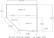
Here's a quick sketch drawn by my friend Thom Mackris for the dual 416 enclosure, showing the plan view, and minus the internal divider mentioned above. One woofer is at 45-degree angle with respect to the rear wall, while the other is at a 5-degree angle. If the speaker pair are 45 degrees apart as seen by the listener, each woofer is 20 degrees off-axis.
Although the theoretical listening angle is commonly considered to be 60 degrees, almost nobody places their speakers that far apart. My own system is pretty unusual in having the Ariels as far apart as they are, in the 50 to 55 degree range, but I've seen high-efficiency speakers as placed as close as 40 degrees or less.
I may settle on slightly different angles for the pair I build for myself, optimized for my listening space, and with the 12.41 inch dimension reduced to 10 inches. The height of the centerline of the AH425 will be at 42 inches, with 1.75 inches of clearance between the top of the cabinet and the lowest point of the horn mouth.
By using separate lowpass filters for each 416 woofer, there's an option of using phase steering for each woofer (effectively moving back in space relative to the other woofer), but that might be more trouble than it is worth. Still, bringing out the wires for each woofer is hardly much trouble, since the crossover is external anyway. The external crossover makes it easy to do subjective tuning at the listening position, with the crossover for each speaker in my lap, and changing component values with jumper wires.
Attachments
Last edited:
The woofers are on the faces marked 17.00, correct?
Nice that you can get away with so "small" a box.
Nice that you can get away with so "small" a box.
(emphasis mine)
And then you go for the man.... not the physics.
But, and I quote,
"Well of course you would. That's what you'd be programmed to say."
Before you reply, have the courtesy of reading what the poster has said at least in this thread before weighing in with an apparently off-the-cuff ad hominem attack.
I did read what he wrote. The statement I was primarily responding to was in a prior post, perhaps I should have quoted that one directly (it's below), but since it was just 2 pages back at the time and it seemed to be a current topic of discussion in the thread I thought I would just reply to that one.
Now he's clearly not a native english speaker, so it's possible he wasn't translating his message correctly. But it seems to be a fairly clear statement below.
My apologies, I got this mixed up with another thing. All this took place quire some years ago. The correct situation is this:
Different cable lengths to two drivers in parallel caused the drivers to not move together. The drivers were each in their individual enclosures.
Concerning two drivers in a single enclosure, if the drivers are different, then they need their individual enclosures. If the drivers are the same, depending on how you stuff the enclosure, you may still want to have individual enclosures. I would use individual enclosures just to avoid the uncertainty. But I can't be sure if it was actually tested or not.
Sorry if my previously post created confusion.
I'm not sure how you are getting an Ad hominem attack out of my post though. I wasn't sure if "Occam's Razor" would translate or he would be familiar with it. So I used the aliens as an example of dragging in something unrelated as an explanation.
If you can explain to me how different lengths of wire would cause that driver behavior, I'm happy to listen to it.
The woofers are on the faces marked 17.00, correct?
Nice that you can get away with so "small" a box.
Yes, the drivers go on the 17" dimension, since they use the late Altec & modern GPA 16" frames. Unlike a midbass driver, there's no need to flush-mount the frames into the front face of the cabinet, which simplifies installation. (On the other hand, recessed mounting is more attractive, and offers a degree of driver protection in shipping and initial setup.)
The adjustable damping of the resistive vent adds an additional degree of freedom to the 2 degrees of freedom of classical vented boxes ... the volume of the box and the vent tuning. Placing the vent on the floor also augments its output ... this is measurable as well as subjective.
Classical vented systems (following T/S design rules) critically rely on amplifier damping for correct synthesis of the highpass filter function. If a zero-feedback triode power amplifier has a 2-ohm output impedance instead of the typical milliohm output impedance of a Class AB transistor amplifier, this has to be allowed for when designing a classical vented box, with QB3 alignments being the most tolerant of variations in amplifier output impedance.
Instead of all the filter damping coming from the amplifier, a substantial part of the damping is provided by the resistance in the vent. It's still a highpass function, most likely in the 4th to 3rd-order range, but the electrical damping (BL product of the driver/amplifier output impedance) is not as critical to the filter tuning.
There's definitely an element of cut-n-try here: you don't really know what it's going to do until the system is measured in-room, since the vent damping is not well characterized mathematically and the effects of floor proximity on the vent don't appear in simulations.
Last edited:
Well, I am sure you have all your reasons; but for the length and application I mentioned, many different material and structure within a specific budget range were tried, did measurements as well as listening, and they track each other. So for me, it is a problem solved. For people whom feel there is no difference, good for you, you also have one less thing to worry about. I believe more exotic material may make some more difference, but it may not be worth spending such money for unless you just have to have it.The thing is you are describing as a source of your problem, something that according to the laws of physics as understood, should have absolutely nothing to do with what you are describing as the problem.
Essentially you are going "I had problem X and did unrelated thing Y which "fixed" it. Therefore Aliens were responsible.".
There are far more likely sources of the problem you describe and that when you made your change to the wire lengths, that you fixed it at the same time.
You tightened the loose connection or replaced a bad wire or soldered things together correctly, etc...
People use mismatched lengths of wire all the time without everything failing to work in the manner that you describe. So the fact that you had a problem with two different lengths of wire and two pieces with the same length didn't, means that something ELSE was the issue.
Copper's electrical characteristics don't change in a noticeable amount over much longer lengths, than in the kind of wire lengths you would have been using.
This is one of the main reasons WHY we use copper for this sort of task (along with it's ductility).
BTW, about the different length issue, this happened after the issue above. Really no more detailed investigation was done. Both enclosures had the same design and drivers, and whatever was inside remained the same, the only thing that seemed possibly were the lengths, is it was just changed to make the lengths the same, and the problem went away. That is the only thing I have one it. My only guess was it effected damping, which seemed to be the case above.
Last edited:
Subjective testing and preliminary measurements on the single-woofer prototype revealed that a box volume of 4.5 cubic feet and a box tuning of 32~34 Hz was a good match for the GPA 416-Alnico woofer. This result might not apply to GPA 416's with ceramic magnets or classic Altec 416's, since the Qts (and efficiency) may be different.
i just saw the drawing for the double gpa416 box and was wondering if you decided to increase the volume for the drivers as the new box appears to be 12cu ft or if shortened in the back and a divider and bracing perhaps 11cu ft which is still a little more then your 4.5 cu ft per driver in your prototype ?
could you tell where the divider between the two drivers goes?
would it cut the volume in half or would you apply different volumes for the two drivers ?
i have an azura horn w/ radian 745 and am playing w/ a prototype bass myself right now .
i am considering buying the gpa alnico drivers and get serious about building new cabinets as long as summer permits and then play with the tuning during the winter , so any details would be appreciated .
best regards
- Home
- Loudspeakers
- Multi-Way
- Beyond the Ariel