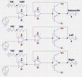
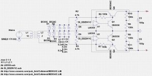
I'm trying to build a power supply using only op amps and discrete components, but I'm having a hard time simulating it when manufacturers don't give full specifications of their products. My primary problem is figuring out a power transformer to use. It'd be easier to simulate and decide if primary inductance, secondary inductance, primary resistance, and secondary resistance were given, but in most cases, they're not. This makes it difficult to choose turn ratio and inrush current limiting thermistors as well as simulating the power capabilities of the circuit overall. I'm trying to build a positive and negative 18V (or a few hundred milivolts less) power supply that can handle a 50W subwoofer amplifier and two 25W full-range amplifiers. The speakers would most likely be 4 ohms each nominally. The input signals would be amplified with an op amp then buffered with an op amp and class B BJT amplifier in the configuration shown in the attachment. I use resistive loads because I don't know how to simulate impeding loads. Also attached is the power supply circuit I came up with. The inductances on the transformer are just examples, but all other components are pretty much set in stone unless a new problem or revelation arises. I'd also add NTC thermistors in series with the primary and secondary windings of the transformer (preferably with a timed bypass switch to allow the thermistors to cool down after doing their jobs, but that's another story). Now then, the questions: how could I accurately simulate the circuit in spice without all the specifications of the transformers being considered? What would the optimal turn ratio of the transformer be? Are there any blatant flaws in my design or improvements I could make to increase efficiency and power capacity?
Attachments
Send me your transformer(s) and I'll measure those characteristics & send them back. I'm near San Francisco, PM for address.
I don't have the transformers. If I did, I would just measure them myself, and there would be no problems. I want to be able to simulate the circuit effectively and accurately before ordering the components, especially transformers as they tend to be pricey compared to other components.
I have gathered data on various types of transformers (split bobbin, toroidal, etc) and derived some average formula's that can predict the principal parameters from the VA rating.
There can be important individual variations of course, but at least it is a starting point.
It is for 50Hz, but some correction factors could translate it to 60Hz.
Tomorrow I should be able to post it
There can be important individual variations of course, but at least it is a starting point.
It is for 50Hz, but some correction factors could translate it to 60Hz.
Tomorrow I should be able to post it
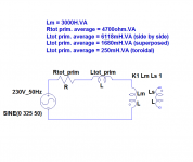
Here are the data. They apply for 230V/50Hz, but they could be extrapolated to 115V by dividing the resulting values by 4.
The 50 to 60Hz change can be adressed by applying an additional 0.83 factor.
Basically, you have to divide the values shown by the VA rating of your transformer to obtain the actual parameter values as seen from the primary (the secondary is supposed perfect).
If you want to spread these values between primary and secondary, in the case of multi-secondaries transformers for example, you have to do it sensibly, based on the voltage and VA rating of each secondary.
Note that these values are very crude approximations, because in actual transformers parameters don't vary in a linear fashion, but they are sufficient to get you going with a simulation and get half-realistic results.
Attachments
You have to use "per unitized" methods to scale transformer parameters. I'm not at my computer right now but look up my transformer posts in the Power Supply Reservoir Size thread, to find a scalable spice transformer model. Or wait until tonight and I will post the links.
I don't mean to revive an old thread, but I wanted to thank Elvee. That formula proves to be fairly accurate, and I've been using it. I appreciate it!
Are there any blatant flaws in my design or improvements I could make to increase efficiency and power capacity?
- I think Q2 needs to be a PNP rather than an NPN as shown.
- I think U2's input terminals are swapped; zener Vref needs to connect to VIN+
- I think R6 and R7 are too large; they set Ic(Q1) = Ic(Q2) = 7uA. Starving these transistors may add excessive amounts of phase shift in the negative feedback control loop of the regulator. I'd boost Ic of Q1 and Q2 by 100X or 1000X.
- I think R8-R11 are too large. They set the impedance of the feedback nodes to 50Kohms; with just 30pF of pin / pcb track / stray capacitance, this creates a pole at only 106 kHz. I'd reduce these to ~ 500 ohms each.
- I am concerned that your regulators' negative feedback control system may not be stable, since it is a cascade of 3 gain stages: Q1 is a CE amplifier / Q4 is another CE amplifier / U1 is an opamp. Av0 is going to be huge, meaning that you're going to need an extremely low frequency dominant pole, much lower than the one built-in to the LM358 opamp. I'd suggest you do a thorough study of phase margin and gain margin (.AC analysis) using lots of different loads, to verify that it's stable under all conditions.
- Finally, a ±18V power supply can deliver, at most, a 12.7V RMS sinewave to a load. If that load is 4 ohms, delivered power is 40.5 watts RMS. You won't get your desired 50 watts using ±18 volts.
- Status
- Not open for further replies.
- Home
- Amplifiers
- Power Supplies
- Transformer Ratings (for Simulation)